Got it, sorry for not remembering that detail. Although it's worth scrolling down -- there's another plot with various loads and cap sizes. Notably, ensuring that there's essentially zero AC voltage across the cap (i.e. keeping the filter frequency very low) seems to be the trick.
That follows from logic.
A cap, or anything else for that matter, can only distort the voltage drop over it. Zero voltage drop, zero distortion can be produced.
It is the ratio between this distorted voltage drop and the voltage drop in the load that determines the end result. If you keep it large enough, you can get away with anything.
Derfy,
What value capacitor do you need to have say 120 dB down voltage across the capacitor at 3,000 hertz with a 10,000 ohm input impedance?
Typical for a CD signal figure .002 volts at both 3,000 and 20 hertz.
I get 80 uF for 20 hertz. Pretty big as a film capacitor.
As an electrolytic with no DC across it....
One of the projects in the back room is rebuilding a Syncon B mixing console. It uses NE5534 opamps with every stage capacitor coupled. As there is no DC across them they turn out to be pretty much the factor that reduces performance.
Why do you need DC blocking caps if there is no DC?
Why do you need 10,000 Ohm input resistance? Use 100K or even more. From an earlier post, I got the impression that you believe this input resistance to be determining the thermal noise level. It does not, it is determined by the KTC noise of the blocking cap and the noise coming from the preceeding stage for all realistic values of said cap.
Since the input resistance will feed the bias current of the opamp, the receiving side typically is somewhat below the sending side. So, mount electrolytics with the plus facing forward, and there should not be a problem. If you want to get wild, you can even first measure in the circuit.
Last edited:
Vaccy,
The point was the blocking capacitors serve no purpose. They were basically designed in as a prior habit.
In a well designed gain stage system, it should be the input stage that limits the noise performance. In audio it is often the audio power amplifier that limits electrical distortion. Of course the loudspeakers clearly have limits, but I suspect the biggest limit is the recording process.
If I understand your comment correctly the Boltzmann constant noise shows up as 1/F noise. Possibly another good argument for a DC compensation servo.
The standards have suggested an input impedance of 10,000 ohms for consumer gear last I looked. Pro gear is of course 600 ohms. (Not really, an obsolete standard.)
Higher impedances are more susceptible to picking up stray noise. The other issue is you frequently want the input bias current multiplied by the input resistor to equal the input offset voltage.
Even with no signal voltage across a component if it is passing current, it might distort the current. Some folks consider the basic elements of circuit theory R, L, C and D!
Now as there is never absolutely no voltage across the capacitor but rather a frequency dependent one there can be intermodulation distortion at usually a very low level from the behavior of the insulator. In a loudspeaker crossover this can be mechanically induced.
Resistors can be very good, capacitors are not quite as good and mis-selected can be bad. Inductors are generally the component that least matches circuit theory. However we have to use what exists.
As Demian pointed out there can be multiple capacitors in series. As their distortion mechanisms may match the distortion can add. So with 10 capacitors in series the distorton instead of being -120 dB down may be only -100 dB.
Last edited:
I haven't seen any pro gear with 600 Ohm input in decades. It's dBu today, boomer. Get with it!
All good fortune,
Chris
All good fortune,
Chris
In Doug Self's preamp published in Linear Audio magazine he uses low impedances to reduce noise and large electrolytic coupling capacitors everywhere. It sounds fine to me.
Vaccy,
The point was the blocking capacitors serve no purpose. They were basically designed in as a prior habit.
So, problem solved, keep'm out.
If I understand your comment correctly the Boltzmann constant noise shows up as 1/F noise. Possibly another good argument for a DC compensation servo.
No, it is very different from 1/f noise, it is the equivalent of thermal noise in resistors, and decreases with admittance. So large caps like used for coupling generate very little noise. It shorts the thermal noise generated by the input resistance, so that the resulting noise is mainly determined by the source.
The standards have suggested an input impedance of 10,000 ohms for consumer gear last I looked. Pro gear is of course 600 ohms. (Not really, an obsolete standard.)
Yes, but there is no reason to have this internal in a piece of gear. But at the interface to the outside world it does. The reason as I see it is that live connections are dangerous to be made with gear with high input impedance. DC bombs and RFI on connecting cables come to mind.
Higher impedances are more susceptible to picking up stray noise. The other issue is you frequently want the input bias current multiplied by the input resistor to equal the input offset voltage.
Yes, but only if they are not properly terminated. The moment a high impedance input is connected to a lower source impedance, the source impedance dominates and determines the noise level.
Even with no signal voltage across a component if it is passing current, it might distort the current. Some folks consider the basic elements of circuit theory R, L, C and D!
Noooooo!!!!
There has to be a voltage over a component, or there will be no distortion. This is basic understanding. The input cap and the input resistance form a voltage divider. If there is no voltage over the cap, only the resistor can contribute to distortion. Every distortion necessitates a voltage differential between input and output of the component (either it will generate one or it just won't be there).
Now as there is never absolutely no voltage across the capacitor but rather a frequency dependent one there can be intermodulation distortion at usually a very low level from the behavior of the insulator. In a loudspeaker crossover this can be mechanically induced.
There is indeed always a voltage across a real life capacitor. Nothing at room temperature will conduct current without developing a voltage over the two terminals. The larger the value of the cap, the lower this voltage. Think in terms of the voltage divider described above. Take a large cap and a large input resistance. There will be little voltage over the capacitor, even at low frequencies.
Resistors can be very good, capacitors are not quite as good and mis-selected can be bad. Inductors are generally the component that least matches circuit theory. However we have to use what exists.
Good or not quite as good, in what terms?
As Demian pointed out there can be multiple capacitors in series. As their distortion mechanisms may match the distortion can add. So with 10 capacitors in series the distorton instead of being -120 dB down may be only -100 dB.
A well proportioned coupling cap does not distort.
Last edited:
?Of course the loudspeakers clearly have limits, but I suspect the biggest limit is the recording process.
For once, you surprise me, Simon. Can you develop? On the paper, mikes are better than speakers, and preamps than power amps.
Last edited:
Why to generalise ? I have often changed electrolytic caps for film ones, with noticeable improvements. As I never tried to measure differences, I don't know if it was noise or distortion (or phases turns due to FC of the high pass filter in case of the Servo VS Cap comparison).A well proportioned coupling cap does not distort.
It seems I'm not the only one to feel the same.
You are moving in circles, this nonexistent "problem" about distortion of coupling capacitors was discussed 8 years ago...
John Curl's Blowtorch preamplifier part II
John Curl's Blowtorch preamplifier part II
John Curl's Blowtorch preamplifier part II
From WJ article "Picking Capacitors"
File Not Found ,
This claim
John Curl's Blowtorch preamplifier part II
John Curl's Blowtorch preamplifier part II
John Curl's Blowtorch preamplifier part II
From WJ article "Picking Capacitors"
File Not Found ,
"capacitor will generate distortion if here is AC voltage dropped across..."
This claim
is 100% valid.. Because here is no significant signal voltage across (properly sized) coupling capacitor, so no signal distortion caused by capacitor. Only feelings without real background. So simple...A well proportioned coupling cap does not distort.
Last edited:
... there is no significant signal voltage across (properly sized) capacitor, so no signal distortion caused by capacitor. So simple...
Simple theory. Only one problem: Some people clearly hear a difference in A/B tests.
When reality doesn't comport with theory, then it has to be theory that is (at least slightly) wrong.
Of course, the theory may be close enough as an approximation for a majority of listeners.
You are moving in circles, this nonexistent "problem" about distortion of coupling capacitors was discussed 8 years ago...
Doesn't hurt to check once in a while to see if there's any breakthrough. Apparently not this time.
Unless you take your expectations for reality.Simple theory. Only one problem: Some people clearly hear a difference in A/B tests.
When reality doesn't comport with theory, then it has to be theory that is (at least slightly) wrong.
Funny how capacitors wake people up
"Call me in Alaska if it all turns out right" (Name that song?)
"Call me in Alaska if it all turns out right" (Name that song?)
This is not a proof, but an opinion.From WJ article "Picking Capacitors"
File Not Found ,
This claim
is 100% valid.. Because here is no significant signal voltage across (properly sized) coupling capacitor, so no signal distortion caused by capacitor. Only feelings without real background. So simple...
Proof of the contrary ? We use caps to build low or high pass filters.
(Your link seems broken, found this one: Picking Capacitors - Walter G. Jung and Richard Marsh )
Last edited:
...Of course, the theory may be close enough as an approximation for a majority of listeners.
I don't believe in democracy in this particular case. 🙂
How about sharing some sound files so we can listen to the differences? Similar to what Pavel did.Why to generalise ? I have often changed electrolytic caps for film ones, with noticeable improvements. As I never tried to measure differences, I don't know if it was noise or distortion (or phases turns due to FC of the high pass filter in case of the Servo VS Cap comparison).
It seems I'm not the only one to feel the same.
This is not a proof, but your opinion.
Proof of the contrary ? We use caps to build low or high pass filters.
Measurements are not my opinion, but a objective fact. But feelings are pure subjective "opinions"..
And using capacitor in low and high pass filters aplications (signal AC voltage across cap) have nothing to do with using the same capacitor in coupling function. You have simply to select proper parts for each aplication.
Last edited:
Measurements are not my opinion...
Okay. Please explain how you are measuring the magnitude of effect of an RC ladder network added to the signal path of an otherwise ultra-low distortion amplifier as it affects time domain linear distortion of a music sample waveform to an accuracy of one part in a million.
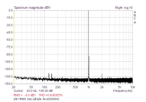
We have to distinguish linear (e.g. BW manipulation) and nonlinear distortion in audio band..😉Linear distortion will be caused even with ideal capacitor. We are talking till now about nonlinear distortion "caused" by (properly sized..) coupling capacitor.
In attached picture You can see "distortion" caused by elyt coupling caps at input and in feedback arm in my amp. 28V RMS output (so quite full voltage swing), no load at output. So no output stage distortions.
In attached picture You can see "distortion" caused by elyt coupling caps at input and in feedback arm in my amp. 28V RMS output (so quite full voltage swing), no load at output. So no output stage distortions.
Attachments
Last edited:
- Status
- Not open for further replies.
- Home
- Member Areas
- The Lounge
- John Curl's Blowtorch preamplifier part III