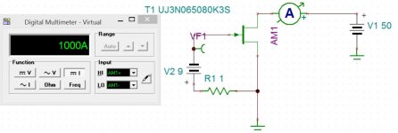
UnitedSIS has a couple of high voltage high power jfets with interesting curves. If you look at this device you see that there are no curves for more than -8v on the gate so I tested one with about -9v on the gate. Using a 110 ohm source resistor to generate the - voltage at the gate I got 9.08 v across this resistor when using 36 vdc on the drain. When I went up to 300V on the drain the voltage across the 110 ohm resistor only went to 9.26V Ok that's not a perfect CCS but it's darn good and it's a cheap $6.09 190w part. https://www.mouser.com/datasheet/2/827/DS_UJ3N065080K3S-1530401.pdf
Interesting indeed. A bit too capacitive for loading a preamp tube but of course can cascode it or use with a low rp power triode. A 6AS7 preamp might work with it.
depletion mode?
Its a JFET, not a MOSFET, it can only be a depletion mode...

Its a JFET, not a MOSFET, it can only be a depletion mode...
thank you, that is what i wanted to hear...
Member
Joined 2009
Paid Member
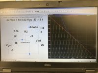
Hi there, I’ve used the spice model they offer and tried this... looks very triode like... very
that’s because of R2 I guess, since a naked JFET is pentode like.
looks very triode like... very
Looks like a 211 curve wise. Except 100X the current. Can make a direct drive SET with an inductor.
that’s because of R2 I guess, since a naked JFET is pentode like.
Yeah, I think so. "Shunt Schade" changing pentodes into triodes. Could also put a TV damper diode under the Source terminal, to get 3/2 power curves instead of 4/2 power curves.
hi there, can you give more details on this toppic pleae?Looks like a 211 curve wise. Except 100X the current. Can make a direct drive SET with an inductor.
Yeah, I think so. "Shunt Schade" changing pentodes into triodes. Could also put a TV damper diode under the Source terminal, to get 3/2 power curves instead of 4/2 power curves.
UnitedSIS has a couple of high voltage high power jfets with interesting curves. If you look at this device you see that there are no curves for more than -8v on the gate so I tested one with about -9v on the gate. Using a 110 ohm source resistor to generate the - voltage at the gate I got 9.08 v across this resistor when using 36 vdc on the drain. When I went up to 300V on the drain the voltage across the 110 ohm resistor only went to 9.26V Ok that's not a perfect CCS but it's darn good and it's a cheap $6.09 190w part. https://www.mouser.com/datasheet/2/827/DS_UJ3N065080K3S-1530401.pdf
nice but too much capacitances.
st has mosfets with <1pf crss
can you give more details on this toppic pleae?
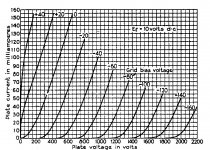
211 tube plate curves below, look similar.
The SIC with 20 Amp curves could be used in a SET like mode (using the R2 'shunt Schade" scheme to get "triode" curves) directly without an OT for impedance transforming. Just would need a high current gapped inductor to a LV "B+" instead of the usual OT primary. A suitable Mosfet will work for Schade "triode" the same way, would be cheaper probably. Could duplicate a 211 SET for 1/100 the price. Will be low 2nd harmonic with such uniformly spaced curves.
If some parallel (to get near a 20 Amp rating!) TV damper tubes were placed in series with the Source terminal, then the gm curves would more closely resemble the 3/2 power law shape of a tube instead of the 4/2 power law of a Mosfet/Fet. (Most -power- tubes are closer to square law, ie. 4/2 power anyway, so not really necessary.)
-----------------------------
nice but too much capacitances.
st has mosfets with <1pf crss
Yes, this part is more suitable for direct speaker drive currents at 100X the current of a typical tube, where its high C would be expected. For tube replacement or tube CCS duty, a smaller SIC FET model is needed, with way less capacitance, especially lower crss for CCS duty.
Attachments
Last edited:
As I recall, Nelson Pass recently stated that he has ordered some of these devices and will report his assessment to us here.
Hi there, I’ve used the spice model they offer and tried this... looks very triode like... very
😀😀😀😀
r1+r2 is the schade fb.....simulating a triode.
3k3/1k = µ3,3

Last edited:
Us opamp guy know that as series feedback. But I like Schade feedback; makes it sound as if it is something new ;-)
Jan
Jan
- Home
- Amplifiers
- Tubes / Valves
- Very interesting CCS device