I read Bateman's article on Amp-Speaker Interactions and found it very interesting that his
Self Blameless amp blew up with a low Zo cable loaded by a speaker load. This gave me a
push to attempt a simulation of the difficult load. I have sims of a Blameless amp, and a
lumped approximation to the load but have been unable to see the destructive oscillation
in simulation. Thought I'd share it so that others can offer opinions.
Ian wrote in Bob Cordell's Book thread: https://www.diyaudio.com/forums/sol...lls-power-amplifier-book-978.html#post5990267
That reminded me of Cyril Bateman's unpublished article on Amplifier-Speaker cable interactions so I forwarded the article to Wayne Kirkwood to update his collection of Cyril's articles here Re: Cyril Bateman Capacitor Sound Archive - Pro Audio Design Forum and the Amplifier-Speaker cable interaction article Parts 1 & 2 (previously only part 1 was available)..
Download here http://www.waynekirkwood.com/images/pdf/Cyril_Bateman/Bateman_Speaker_Amp_Interaction.pdf
Cyril mentions some RF injection tests on an amp in the article.
Although this is not an easy read it contains some vital information for amplifier builders that few seem to be aware of - the need to add a termination Zobel at the speaker terminals. Bob Codell mentions this in his book but I can't find any previous mention of this on this forum (I don't have page reference for 2nd ed right now, maybe someone can give it).
Why is a speaker cable termination Zobel needed? That's what Cyril tried to explain but never quite uncovered the source of the amplifier oscillation that destroyed 3 of his amps (2 while bench testing with different cables). But he did prove
1) using measurements that the reflected energy from an unterminated speaker cable presents a high return ratio (a transmission line engineers term) and the amplifiers Zobel, and
2) the output inductor does not stop amplifiers from oscillating at a few MHz, and this can destroy some amps (his BJT amps failed but not his lateral amps).
I believe it is as serious as that. It requires more research to get to the bottom of what causes this and maybe if amplifiers can be made that don't oscillate when driving problematic unterminated speaker cables. Is it as simple as adding heavier compensation?
Cheers,
Last edited:
I was unable to find a schematic for the exact Blameless implementation that Cyril used in
his testing, and took a guess that it might be this schematic:
https://www.diyaudio.com/forums/att...dells-power-amplifier-book-self_ch22_fig4-jpg
his testing, and took a guess that it might be this schematic:
https://www.diyaudio.com/forums/att...dells-power-amplifier-book-self_ch22_fig4-jpg
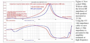
Figure 4 in the article shows the input impedance of the low Zo #55 cable loaded by the
actual speaker in red and a simulation in blue:
https://www.diyaudio.com/forums/attachment.php?attachmentid=800965&d=1575945734
actual speaker in red and a simulation in blue:
https://www.diyaudio.com/forums/attachment.php?attachmentid=800965&d=1575945734
Attachments
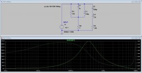
Here's a lumped approximation that I made with a parallel RLC for the peak and a series RLC
for the HF dip. R1 is the height of the peak, R2 is the low frequency Z, R3 is the HF dip in
impedance. The Ls and Cs are chosen to hit the frequency of the peak and dip with the ratio
controlling the Q of the resonances. It turns out that the series RLC is capacitive below
resonance and provides enough so that C1 becomes a place holder:
The results look good and even the phase is close to the actual circuit.
Attachments
Here's a .zip file of the Blameless 50W simulation with the low Zo and speaker test load.
It does not oscillate in simulation without a drastic change such as reducing the Cdom cap.
The semi models are all from Bob's file but I also tried some older output devices that are
also included but I don't know if those models are good.
Perhaps others will take a look at it with constructive comments.
Attachments
Hi Pete,
Thanks for starting this thread. Thanks for the simulation.
I added Zobel and inductor parasitics from Cyril's Cap2.tif.
Added a resistor on the input that was found necessary to stop oscillation of the EW PCB (reported by Forr etc). The updated file is attached.
I also a resistor to the collector of Q4 that should be present to limit driver current and dissipation when clipping. Recovery of the VAS from hard saturation after clipping can cause ringing which requires heavier compensation than non-clip operation. This Self design does not seem to need this resistor to limit driver dissipation so it is disabled for the purposes of establishing a cable induced oscillation.
The circuit still doesn't oscillate but there is some indication from clip recovery that it would oscillate at 3MHz if there was a little more phase shift around that frequency. One possibility is quasisaturation in either the VAS or the power transistors and drivers (or various combinations) because Cyril saw oscillations starting just after leaving the positive peaks. Quasisaturation is tricky to model, particularly the HF part. The standard models like Bob Cordell's do not include quasisaturation. Another possibility is various inductances in the PCB. I found this in one of my PCB's where only 1cm of track in a driver emitter return to common upset stability.
I'm not sure we can get oscillation with LTspice software as our models are inadequate and PCB likely inductances (and mutual-couplings) are hard to incorporate in a realistic way.
There is still the question of the Maplin lateral amp and why it oscillated since it is a completely different topology. There could be some common issues like quasisaturation of the BJT's in the lateral amp and/or PCB inductances.
It would be nice if there is a simple explanation of why Cyril's #55 5m cable caused oscillation (and the 79 strand 10m zip) and maybe a simple cure for amps (other than adding the 2nd termination Zobel at the other end at the speaker).
Attachments
Last edited:

Hi Pete,
Thanks for starting this thread. Thanks for the simulation.
I added Zobel and inductor parasitics from Cyril's Cap2.tif.
Added a resistor on the input that was found necessary to stop oscillation of the EW PCB (reported by Forr etc). The updated file is attached.
I also a resistor to the collector of Q4 that should be present to limit driver current and dissipation when clipping. Recovery of the VAS from hard saturation after clipping can cause ringing which requires heavier compensation than non-clip operation. This Self design does not seem to need this resistor to limit driver dissipation so it is disabled for the purposes of establishing a cable induced oscillation.
The circuit still doesn't oscillate but there is some indication from clip recovery that it would oscillate at 3MHz if there was a little more phase shift around that frequency. One possibility is quasisaturation in either the VAS or the power transistors and drivers (or various combinations) because Cyril saw oscillations starting just after leaving the positive peaks. Quasisaturation is tricky to model, particularly the HF part. The standard models like Bob Cordell's do not include quasisaturation. Another possibility is various inductances in the PCB. I found this in one of my PCB's where only 1cm of track in a driver emitter return to common upset stability.
I'm not sure we can get oscillation with LTspice software as our models are inadequate and PCB likely inductances (and mutual-couplings) are hard to incorporate in a realistic way.
There is still the question of the Maplin lateral amp and why it oscillated since it is a completely different topology. There could be some common issues like quasisaturation of the BJT's in the lateral amp and/or PCB inductances.
It would be nice if there is a simple explanation of why Cyril's #55 5m cable caused oscillation (and the 79 strand 10m zip) and maybe a simple cure for amps (other than adding the 2nd termination Zobel at the other end at the speaker).
Nelson Pass wrote about terminating with a zobel network at the speaker I tried this at the time - that is nearly 40 years ago. For what it is worth see
PassDiy
Nelson Pass wrote about terminating with a zobel network at the speaker I tried this at the time - that is nearly 40 years ago. For what it is worth see
PassDiy
This was talked about in Bob's book thread, people have been suggesting 100 ohms or
100 + a series cap for many, many years. Still it would be better for the amp to be stable
even without the termination.
This was talked about in Bob's book thread, people have been suggesting 100 ohms or
100 + a series cap for many, many years. Still it would be better for the amp to be stable
even without the termination.
You did raise the question about Miller Inclusive Compensation in a recent post. You can lead a horse to water....
- Home
- Amplifiers
- Solid State
- Simulation: Cyril Bateman's Amplifier-Speaker cable interactions