Bob Cordell, in his VinylTrak article cited Doug Self's May 2012 Elektor article: "Preamplifiers 2012" as an example of using synthetic loading to militate against the noise of the 47k load resistor.
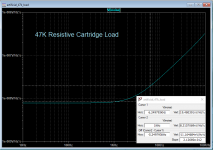
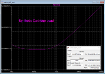
Using the values from the Elektor article I simulated the response. It seems to me that the synthetic load over-damps the cartridge.
Someone clue me in:
Using the values from the Elektor article I simulated the response. It seems to me that the synthetic load over-damps the cartridge.
Someone clue me in:
Attachments
Did you read the addendum Bob put on his website?
There was some discussion on this a couple of years back on one of the the meandering cartridge threads but that was looking at the noise penality of loading the cartridge down to create the 75us pole.
There was some discussion on this a couple of years back on one of the the meandering cartridge threads but that was looking at the noise penality of loading the cartridge down to create the 75us pole.
> Using the values from the Elektor article
I do not have the Elektor article. Looking at Cordell's site, I see gain of -10 and 511k. So I can't figure how you came up with gain of -159.5.
By caveman thinking, the gain should be about as much as you increased the resistor. Cordell's 511k divided by apparent Gv=-10 is 51.1k, close. The full derivation has a subtract-one in it. 511k/11 is 46.45k, real close. Conversely, your 1Meg divided by your -159 looks like ~~6k; sim says 6.23k, which is indeed more damping than 47k. Your R13 100r (default?) should be about 786.662 Ohms, though you might want to re-rationalize R11:R13 to simpler values.
While the final answer is "damping", the basic question is "how to fake 47.0k with a bigger resistor?". Don't need many parts to sim that. My sim has a GAIN block; a source, a GAIN, and a resistor does the job. (Exactly, without any quibble about a LT115's imperfections; though these should be accounted before you order resistors).
Don't forget, if you have 430k in front of this, you really want to aim for 52.767k (430k||52.767k=47k). And 430k is not-huge compared to 47k. There's probably another part-dB noise figure if you go much bigger. OTOH cap-leakage may happen.
Attachments
Last edited:
> Using the values from the Elektor article
I do not have the Elektor article. Looking at Cordell's site, I see gain of -10 and 511k. So I can't figure how you came up with gain of -159.5.
Don't want to step on the good Dutch folks IP from Elektor, or Self's work -- but these are the values which were in the schematic of the article and not original to me.
Interesting. I'm wondering why one would need to synthesize the 47k loading. In terms of noise, it's in parallel with the ESR of the cartridge, thereby having negligible contribution. You only hear the 47k if nothing is connected to the input.
The synthesis seems reasonable, except for potential stability problems caused by opamp phase shifts at higher frequencies.
Yeah, I don't get it. So much extra circuitry to solve a non-issue...
The synthesis seems reasonable, except for potential stability problems caused by opamp phase shifts at higher frequencies.
Yeah, I don't get it. So much extra circuitry to solve a non-issue...
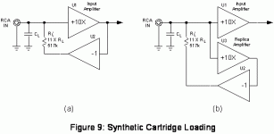
Synthesised 47k is pretty pointless. 6k is rather more useful IF you want to do the damped loading Bob talks about. It neatly sidesteps the capacitive loading issues, but does require a somewhat more accurate measurement of the cartridge than the manufacturers specs. Would be almost impossible to make a commercial product with this but for the commited DIY type its a valid approach.
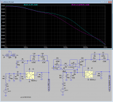
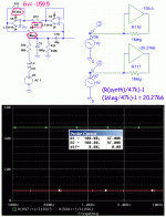
Bob Cordell, in his VinylTrak article cited Doug Self's May 2012 Elektor article: "Preamplifiers 2012" as an example of using synthetic loading to militate against the noise of the 47k load resistor.
Using the values from the Elektor article I simulated the response. It seems to me that the synthetic load over-damps the cartridge.
Someone clue me in:
The gain for synthetic load should be -20x.
1M = 47K + 953000.
Gain = - 953000/47K = -20.276x
The gain for synthetic load should be -20x.
1M = 47K + 953000.
Gain = - 953000/47K = -20.276x
Mr. Self was off by 10X
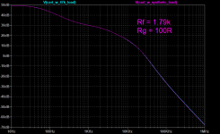
Taking @PRR comment into effect, we are actually looking for 47K = 430k||Rx, Rx = ~ 52.7k.
This looks better:
Attachments
That's a good idea, as an LT1115 would produce far more noise current than the 0.5869 pA/sqrt(Hz) of a 47 kohm shunt resistor.
Interesting. I'm wondering why one would need to synthesize the 47k loading. In terms of noise, it's in parallel with the ESR of the cartridge, thereby having negligible contribution. You only hear the 47k if nothing is connected to the input.
The synthesis seems reasonable, except for potential stability problems caused by opamp phase shifts at higher frequencies.
Yeah, I don't get it. So much extra circuitry to solve a non-issue...
Taking into account the 500 mH or so of the cartridge, the noise current of the 47 kohm shunt resistor is usually the biggest noise source in the whole amplifier - though usually still small compared to record surface noise, so if you don't care about the noise in between records, you can still regard it as a non-issue.
I wrote an article in 2003 showing that optimizing the RIAA- and A-weighted noise is essentially the same as optimizing the spot noise at 3852 Hz. At 3852 Hz, a cartridge with 500 mH of inductance has about 12 kohm of impedance. The sqrt(4 k T/R) ~= 0.5869 pA/sqrt(Hz) of noise current injected by the 47 kohm shunt resistor then has the same impact as 0.5869 pA/sqrt(Hz) * 12 kohm ~= 7 nV/sqrt(Hz) of equivalent input noise voltage.
I wrote an article in 2003 showing that optimizing the RIAA- and A-weighted noise is essentially the same as optimizing the spot noise at 3852 Hz. At 3852 Hz, a cartridge with 500 mH of inductance has about 12 kohm of impedance.
Elektor, Audio Xpress, JAES ? -- couldn't find it. Always anxious to learn!
Some of us are of course odd and have MM cartridges well under 100mH 🙂
Grado?
Linear Audio | your tech audio resource is the article Marcel was talking about.
I don't have a grado, but the 85mH Signet TK9 and 40mH panasonic EPC205CII-L
I don't have a grado, but the 85mH Signet TK9 and 40mH panasonic EPC205CII-L
Interesting. I'm wondering why one would need to synthesize the 47k loading. In terms of noise, it's in parallel with the ESR of the cartridge, thereby having negligible contribution. You only hear the 47k if nothing is connected to the input.
Untrue. The cartridge impedance rises with frequency, being over 50k inductive at 15kHz using that 600mH model. The 47k load resistor is very noticable at that frequency. Doing a Spice noise analysis of that model is informative.
MM cartridges are highly inductive (ever taken one apart?), so the shunting effect of the cartridge ESR on the 47k resistor only operates at lower frequencies. Above about 2kHz with that 800Ω+600mH model the 47k resistor is dominating Johnson noise. The current noise of the amp will interact with it and the cartridge impedance to produce noise too.
The increasing noise with frequency is mitigated by the RIAA response, but that doesn't stop the 47k being more important at HF for noise than the cartridge ESR, both for Johnson and current noise.
Using a synthesized load means the Johnson component of that noise can be knocked right down. You still have to ensure the amp's current noise is low as that multiplies into any impedance, synthesized or ohmic or reactive.
Last edited:
....You only hear the 47k if nothing is connected to the input....
Agree; at least, needle off the vinyl.
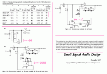
Yet a couple fine designers have worked this field. Doug Self's 2010 book has a table which I take the liberty to post. He computes a couple-dB less noise with synth load, only after amplifier hiss is pushed way down. (Even with '5532 the gain is under 1dB.)
He also shows the Basic, the van de Gevel, and his own plan. The vdG has the elegant detail of NFB resistor also setting cooler gain. Self separates the two jobs but this adds an opamp. (There is MUCH more in the book; everybody should have it handy.)
All these examples use gain about 20, which makes sense: 1Meg/20 is 47k. Higher gain might be used with much larger resistance.
Attachments
Last edited:
Mr. Self was off by 10X
Taking @PRR comment into effect, we are actually looking for 47K = 430k||Rx, Rx = ~ 52.7k.
This looks better:
No. Please read Douglas Self's book: Small Signal Audio Design, 2 Edition.
Yes, the original was in EW -- I should've searched more diligently!
Yes, the 2003 Electronics World article was what I wrote about, the later Linear Audio article is an extension to other noise weightings and to systems using the cartridge inductance to make the 75 us time constant.
Untrue. The cartridge impedance rises with frequency, being over 50k inductive at 15kHz using that 600mH model. The 47k load resistor is very noticable at that frequency. Doing a Spice noise analysis of that model is informative.
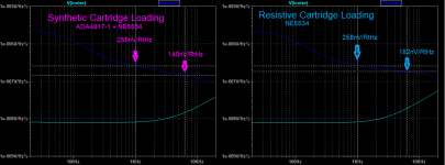
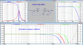
A cartridge is a somewhat more complex model than you are assuming. Hans Polak did some measurements on another thread. Attached is an example of a fairly normal MM up to generator resonance.
Attachments
- Home
- Source & Line
- Analogue Source
- Synthetic Cartridge Loading