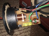
Guys need help in finding out crossover layout. I can't understand the scheme fully especially in tweeter region.
As far as i can understand woofer works in that way:
As far as i can understand woofer works in that way:
An externally hosted image should be here but it was not working when we last tested it.
Attachments
Guys need help in finding out crossover layout. I can't understand the scheme fully especially in tweeter region.
As far as i can understand woofer works in that way:
That looks reasonable.
From the photos I'd say it's a pretty standard second order crossover. The resistors are likely for level adjustment.
If you trace the foil from the binding post, you will likely find a capacitor in series with a coil to ground... maybe a couple of resistors, leading to the tweeter.
If you trace the foil from the binding post, you will likely find a capacitor in series with a coil to ground... maybe a couple of resistors, leading to the tweeter.
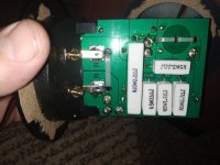
I can't make out what 3 resistors do in tweeter network.
An externally hosted image should be here but it was not working when we last tested it.
Need better (up close) photos from multiple angles of both of the board sides.
Attachments

One Suggestion;
Un-solder one end of each of those 5 resistors (& then stand them up towards the camera to minimize their profile within your next camera shot ).
Anyone helping you needs to see ( an unrestricted ) view of the backside of that PC board.
Use Hemostats as a heat-sink ( and gripper ) to pull free ( from the PCB ) the heated end of each resistor.
🙂
Anyone helping you needs to see ( an unrestricted ) view of the backside of that PC board.
I will try it later 🙂. Resistors are glued to the board very tightly.
Terminals is glued tightly. I pulled one out with some effort but the second one is fixed dead. What the hell Dynaudio? What is the sense in gluing terminals?
Don't know what to do. May be hairdryer will help?
Don't know what to do. May be hairdryer will help?
Terminals is glued tightly. I pulled one out with some effort but the second one is fixed dead. What the hell Dynaudio? What is the sense in gluing terminals?
Don't know what to do. May be hairdryer will help?
I see 5 resistors ( obscuring one's vision ) on that PC board.
Why are you now talking about 2 Terminals?
Back to the beginning, once the schematic is fleshed out, what do you intend to do with that information?
🙂
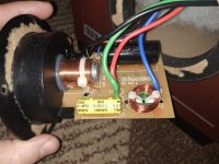
Poly cap high passes with small air coil, air coil goes to (-) via the 1.2 ohm ressitor. The output of this goes to the tweeter via the 2.7 ohm resistor.
Akarma, you shouldn't need to pull it apart if you can poke around it with your meter, unfortunately we can't do that.
Akarma, you shouldn't need to pull it apart if you can poke around it with your meter, unfortunately we can't do that.
As the tweeter has probably more sensitivity, the resistors are there to form an L-pad in order to attenuate it.
Why are you now talking about 2 Terminals?
I want to pull second terminal plate out of the speaker but can't do it. It is glued in its position very tightly. I saw many speakers but glued terminal plate is something new.
Back to the beginning, once the schematic is fleshed out, what do you intend to do with that information?
🙂
I want to upgrade crossover a little bit 🙂. I have measured speakers and found out that DM 3/7 has some potential (good cabinets, high quality speakers) but crossover is not optimal.
Poly cap high passes with small air coil, air coil goes to (-) via the 1.2 ohm ressitor. The output of this goes to the tweeter via the 2.7 ohm resistor.
Yep. I came to the same conclusion 🙂. The only thing i don't understand is R4 0.33Ohm resistor.
Where does the input side of the poly cap connect
Input +.
Is it 0r33, or 33
5W33Ohm. It looks like 33Ohm 🙂 It is strange but when i've measured resistor with multimeter it shows 4.3-4.2Ohm 😕
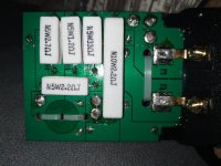
Ok, I can barely see it but it seems the 33 goes directly in parallel with the tweeter. This way, your meter is seeing it in parallel with each of the resistance of the other two resistors and the inductor in series.
Now, the smaller 2.2 looks to come from the (+) terminal. Where does the other end go?
Now, the smaller 2.2 looks to come from the (+) terminal. Where does the other end go?
Now, the smaller 2.2 looks to come from the (+) terminal. Where does the other end go?
Yes. I think it goes to poly cap 12uF
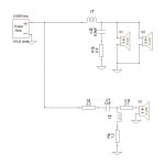
I can't see exactly where other end of R4 goes. But I think it should be like this:
An externally hosted image should be here but it was not working when we last tested it.
- Home
- Loudspeakers
- Multi-Way
- Dynaudio DM 3/7 crossover scheme