Okay so here's a total noobstorm:
I got this chinese douk-audio EL34 SE amplifier and I realize today that either something is off with the OT wiring 😱 - or I am going crazy...
This is how it's supposed to look like:
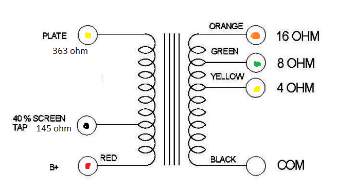
I measure 363ohms accross the entire primary and 145ohm from the screen tap to the B+. However the plate was attached to to the black wire which is supposed to be the screen and the G2(screen) was attached to the yellow wire which is supposed to be vice versa.
The UL tap is supposed to be closer to the B+ and measure less impedance right ? I mean how the hell did this even work...!?
By the way, since the UL tap is closer to the B+ doesn't this mean that G2 has higher idling voltage than the plate ?? This is so confusing to me since in triode mode it's the opposite. Right ? Am I missing someting ?? Sorry and thanks!
I got this chinese douk-audio EL34 SE amplifier and I realize today that either something is off with the OT wiring 😱 - or I am going crazy...
This is how it's supposed to look like:
I measure 363ohms accross the entire primary and 145ohm from the screen tap to the B+. However the plate was attached to to the black wire which is supposed to be the screen and the G2(screen) was attached to the yellow wire which is supposed to be vice versa.
The UL tap is supposed to be closer to the B+ and measure less impedance right ? I mean how the hell did this even work...!?
By the way, since the UL tap is closer to the B+ doesn't this mean that G2 has higher idling voltage than the plate ?? This is so confusing to me since in triode mode it's the opposite. Right ? Am I missing someting ?? Sorry and thanks!
Attachments
Factory assembly error that they barely checked for proper operation (if at all).
Are both channels wired the same way?
Are both channels wired the same way?
Both channels were. I actually discovered this in the process of adding a triode/UL switch. And I actually totally flipped when i measured the G2 current which was at 50mA !!!
But it's sooo weird because I really dont like how it sounds in UL now, it sounds very edgy glassy and harsh.
But it's sooo weird because I really dont like how it sounds in UL now, it sounds very edgy glassy and harsh.
Both channels were. I actually discovered this in the process of adding a triode/UL switch. And I actually totally flipped when i measured the G2 current which was at 50mA !!! But it's sooo weird because I really dont like how it sounds in UL now, it sounds very edgy glassy and harsh.
Use it in triode mode until the factory replies about the situation (if they ever do).
The winding resistance is not always an indication of the actual turns ratio. For example it may be possible to have two separate windings one for the plate and one for the screen both starting from the B+. The screen may use thinner wire. Would be very unusual and not how its drawn and I don't think thats the case. If you want to be sure and you have a sig gen then you could measure turns ratio say at 200Hz. Could be connected up wrong in which case all sorts of funny things will happen.
Here's an idea to test. Put the speaker on the correct output and only do this in triode mode. Try the plate and screen on the black wire, then try it on the yellow wire. With any luck one should be louder than the other. With the plate on the 40% tap I would expect much less power transfer I think. Remove NF when doing this.
Oddly enough if you swap the UL and plate over it still works in simulation with a small HF oscillation and poor distortion.
Last edited:
Both channels were. I actually discovered this in the process of adding a triode/UL switch. And I actually totally flipped when i measured the G2 current which was at 50mA !!!
But it's sooo weird because I really dont like how it sounds in UL now, it sounds very edgy glassy and harsh.
50mA into the screen is hard to believe even with plate and screen reversed, unless you inadvertently disconnect the plate, in which case the tube will die within seconds. No EL34 can survive 20W+ of screen dissipation ...
Happens easily when you first measure plate current with an Amp Meter and then turn to screen current while forgetting to reconnect plate ... You do that only once though ...
And yes, still somehow works with cross connected UL but the screen now gives positive feedback when it should provide negative, hence the ringing.
50mA into the screen is hard to believe even with plate and screen reversed, unless you inadvertently disconnect the plate, in which case the tube will die within seconds. No EL34 can survive 20W+ of screen dissipation ...
You're right, i was actually measuring the plate current and it is at that point that I realized something was off with the wiring.
The winding resistance is not always an indication of the actual turns ratio. For example it may be possible to have two separate windings one for the plate and one for the screen both starting from the B+. The screen may use thinner wire. Would be very unusual and not how its drawn and I don't think thats the case. If you want to be sure and you have a sig gen then you could measure turns ratio say at 200Hz. Could be connected up wrong in which case all sorts of funny things will happen.
The picture is not of the actual winding, I just used it to present how the OT measures.
So, I'm still trying to clear this up:
The UL tap is closer to B+ than the plate right ? and thus measures less impedance and more voltage?? right ?? What am I missing?? How can the G2 have higher idle voltage than the plate ??
Please tell me how am I wrong here
Determining the true orientation of the winding, try inserting a low voltage at the speaker terminals, say, 6V from a heater secondary. Then, measure the primary voltages and then take the ratio from them. DC resistances may vary widely with winding technique. Take care that voltages so measured may be around 200 or more volts.
Thanks, I may try that but shouldn't that present alot more voltage on the primary. The turns ratio is 30, it's a 3.5K:0-4-8 tranny.
But what if I just apply voltage to B+, shouldn't the UL tap measure less than the plate one ??
But what if I just apply voltage to B+, shouldn't the UL tap measure less than the plate one ??
No with DC, for DC a trafo is only a piece of copper wire. Trafos work only in AC or variable DC voltage (or an AC and DC summed). Only transmit variable voltages/currents, not the steady ones.
Thanks, I may try that but shouldn't that present alot more voltage on the primary. The turns ratio is 30, it's a 3.5K:0-4-8 tranny.
But what if I just apply voltage to B+, shouldn't the UL tap measure less than the plate one ??
Yes.
When you measure DCR on a coil, remember you are measuring the resistance on the enameled copper wire, which is not synonymous with turns. As the coil fills up a turn require more wire, i.e. more DCR. Sure, it is a good start, and the transformers may have been wired wrong, but the "induce small AC and measure" is a better and more conclusive test. HTH
Swapping g2 and anode OPT wires will not cause positive feedback. It will cause too miuch negative feedback. However, this may cause instability problems near the OPT HF resonance.Sorento said:And yes, still somehow works with cross connected UL but the screen now gives positive feedback when it should provide negative, hence the ringing.
When correctly wired, the g2 tap will be at a slightly higher DC voltage than the anode connection.
That's exactly what a simulation showed. I guess then you could safely swap the wires over and try to see if the UL works properly.
> How can the G2 have higher idle voltage than the plate ??
EL34 is not a True Tetrode. The main point of any Pentode (or beam) is that Plate CAN swing far below G2 without an abrupt drop of plate current. That's why we pay the buck for a G3 (or beam rod). That's why the type 24 is obsolete, and True Tetrodes retreated to very high power RF amps where Plate voltage may be far-far higher than G2 voltage.
Occasionally (rarely) you see a 6L6 working as a resistance coupled video 'scope amplifier with Plate at 150V and G2 at full 300V.
In ANY pentode Power amplifier, half the time the plate is swung far below G2, even below 100V.
When there is no separate G2 filter (or in simple UL), G2 "must" idle a few volts higher than plate due to 5V-20V drop along the plate winding.
When correctly wired, the g2 tap will be at a slightly higher DC voltage than the anode connection.
>
When there is no separate G2 filter (or in simple UL), G2 "must" idle a few volts higher than plate due to 5V-20V drop along the plate winding.
Thank you all! Well, this confirms my belief that the OT's were incorrectly wired. G2 does idle couple of volts higher after I swapped the terminals.
Important observations/NOTES:
- There is much less distortion in triode mode and a tad more power. - I'm not surprised at all
- The power and volume gain are very noticeable now when switching from TR -> UL (before there was no change in volume). I'm moderately surprised
- Now it definitely sounds worse than before when it's in UL - the sound is very edgy and harsh and the low end is somehow convoluted/cramped 🙁. Here I'm totally confused 😕
I'm wondering ... Could it just be poor quality OTs??
Last edited:
Super don't know UL sounds not so good. Did you move the speaker output tap when it was wrong to compensate? Maybe the switch is also wired wrong!
Maybe the switch is also wired wrong!
Good point, better check that.
Swap the two G2 leads. Is that better or worse?
In normal UL we have NFB through G2. Smoother, more polite.
If we swop G2 between sides we have Positive feedback. Harsher! (In an extreme it could howl, which would have been a clue, but the usual UL ratio won't go that far.)
You could also measure Ohms tap to tap. You expect like P1-100r-S1-100r-CT-100r-S2-100r-P2. If you get something like that except S1 and S2 swapped, suspect they didn't label the wires well at all.
- Home
- Amplifiers
- Tubes / Valves
- UL Tap idling voltage in SE