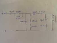
Here is the midrange crossover. I'd like to ask
1. What are the components of the high pass section?
2. How many orders of this filter? Is it 3rd order on both low pass and high pass with impedance equalization network or 3rd on high pass and 4th on low pass?
Thank you
1. What are the components of the high pass section?
2. How many orders of this filter? Is it 3rd order on both low pass and high pass with impedance equalization network or 3rd on high pass and 4th on low pass?
Thank you
Attachments
Edit: Allen beat me to it. Leaving up for whatever it's worth:
To a point it depends how pedantic you want to be, since all of them impact the behaviour -it's a question of what and how much.
That's the pedantic version. On the face of it, the high pass appears to be a damped 3rd order electrical formed by the two series caps and the shunt LC. Then a modified 3rd order electrical low pass, the primary being shunted with a resistor to shape the response. The RC is likely a Zobel impedance flattening variation but this is all conjecture without knowing anything about the drivers or their on-baffle frequency, impedance & phase responses.
Thank you for the answers. I try to understand the band-pass crossover design. I'm an amateur. Sorry for my English.
Here is the midrange crossover. I'd like to ask
1. What are the components of the high pass section?
2. How many orders of this filter? Is it 3rd order on both low pass and high pass with impedance equalization network or 3rd on high pass and 4th on low pass?
Thank you
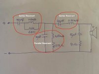
This is a very complex filter. I've done some markup on the original drawing to break it down.
The first cap and coil form a series resonant circuit.
The second cap and coil form a parallel resonant circuit.
The third cap and coil form another series resonant circuit.
Capacitors conduct more current as frequency increases.
Inductors (coils) conduct less as frequency increases.
When you hook them in series, the capacitor begins to conduct and so does the inductor, at some point significant current is passed to the midrange driver. As frequency increases more, the capacitor becomes saturated but the inductor begins blocking current. This creates a resonant circuit that only conducts over a narrow range of frequencies.
When you hook a cap and a coil in parallel the oppsite happens. At low frequencies the coil conducts heavily, in this case shunting any leakage from the first series circuit to ground. As the frequency increases the coil begins to conduct less but the capacitor is conducting more. As they enter their resonant frequencies, where the coil and cap are conducting equally, the least current passes through allowing it to pass to the next filter. Above their resonant frequency the capacitor is conducting heavily taking leakage current from the first filter to ground.
The second series resonant circuit acts like the first, passing current to the midrange driver only in it's resonant frequency band.
So this is actually a 3rd order bandpass filter.
The final cap and resistor form a high pass filter that shunts some current to ground at the top of the bandpass frequencies, probably to even out the response a bit.
There... is that confusing enough? 😉
You can read more about resonance and filters at All About Circuits
Attachments
Last edited:
Thank you for the answers. I try to understand the band-pass crossover design. I'm an amateur. Sorry for my English.
There's nothing wrong with your English.
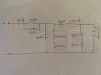
Perhaps the attached may help a little more.
An electrical bandpass filter is 'simply' a filter that electrically rolls off both the high and low frequencies.
-The components within the green boxes form a 3rd order electrical low-pass. The only modification to a regular 3rd order electrical is that the first inductor is shunted with a resistor; this will be used to help shape the response.
-The components within the red boxes form a 3rd order electrical high pass. I don't know if the 0.56ohm resistor is 'real' or simply represents the resistance of the coil; either way, it is just providing a little subtle shaping of the response; possibly some damping around the filter corner frequency.
-The components within the yellow box appear to be a straightforward Zobel intended to flatten the rising voice-coil impedance.
Attachments
Last edited:
There's nothing wrong with your English.
Perhaps the attached may help a little more.
-The components within the green boxes form a 3rd order electrical low-pass. The only modification to a regular 3rd order electrical is that the first inductor is shunted with a resistor; this will be used to help shape the response.
-The components within the red boxes form a 3rd order electrical high pass. I don't know if the 0.56ohm resistor is 'real' or simply represents the resistance of the coil; either way, it is just providing a little subtle shaping of the response; possibly some damping around the filter corner frequency.
-The components within the yellow box appear to be a straightforward Zobel intended to flatten the rising voice-coil impedance.
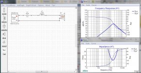
Nope. Those are actual bandpass filters, as I marked them in my response.
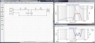
The first thumnail demonstrates series resonance... notice how the frequency response peaks as the impedance dips.
The second thumbnail demonstrates parallel resonance ... notice how the frequency response peaks as the impedance rises.
When we combine them in the third thumbnail, we get the narrow band response as shown.
Crossovers are filters... first and foremost. Filter theory is a bit complex but it is well worth understanding. It will help you make better crossovers ... All About Circuits
Attachments

Last edited:
I think the green boxes on the right are swapped?
Yes, quite right, my apologies, this is what happens when you try to do something useful when you're down with stomach 'flu. Re the above, while the component order in the circuit the OP indicates does have an influence, the basic principle is as noted in standard audio parlance, and we don't really break it down excessively into the absolute basics unless an education in basic filter theory is requested, and if we're going to go down that route, we should be further pointing out that MC drive units are themselves electromechanical bandpass devices, and all filters, high, low or 'bandpass' can be described as a form of bandpass filter if you stretch the definition far enough.
Last edited:
- Home
- Loudspeakers
- Multi-Way
- Order of this midrange crossover