Hi,
I have 40 years old active 3 way speakers and the problem is the amplifiers/motherboards are in the end of its lifespan.
All the time something broken.
So what i want is to use from the plate is the power dc +-36v and the active crossover and get the signal from that to a new&better sounding amplifiers.
Signal path is standard: balanced input - crossover - each individual amp (bass - mid- treble)
So i need the signal from the board somewhere before the amps.
I have two examples of schemantics,
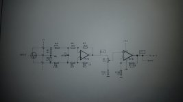
First is the input from Xlr to 10k input potentiometer &12db buffer IC
Second is a tweeter amp
I have located the c10 from the plate, the "entrance" to the amp.
First question:
Is it at the c10 tweeter signal + and the ground is tweeter -??
So wires from these two points to the new amp gives me signal i need?
Second one:
If my new amp has balanced xlr in, how do i get balanced xlr out from these two?
Or where and how do i get it?
I have 40 years old active 3 way speakers and the problem is the amplifiers/motherboards are in the end of its lifespan.
All the time something broken.
So what i want is to use from the plate is the power dc +-36v and the active crossover and get the signal from that to a new&better sounding amplifiers.
Signal path is standard: balanced input - crossover - each individual amp (bass - mid- treble)
So i need the signal from the board somewhere before the amps.
I have two examples of schemantics,
First is the input from Xlr to 10k input potentiometer &12db buffer IC
Second is a tweeter amp
I have located the c10 from the plate, the "entrance" to the amp.
First question:
Is it at the c10 tweeter signal + and the ground is tweeter -??
So wires from these two points to the new amp gives me signal i need?
Second one:
If my new amp has balanced xlr in, how do i get balanced xlr out from these two?
Or where and how do i get it?
An externally hosted image should be here but it was not working when we last tested it.
An externally hosted image should be here but it was not working when we last tested it.
The images are not in their proper format. Read the manuals on this platform.
We're happy to help you.
Cheerio,
We're happy to help you.
Cheerio,

Yes the input to C10 and ground are the signal to that power amp.
You can created an unbalanced differential signal on XLR by connecting the cold pin to ground, hot pin to single-ended signal. Its not great, but it will work. Otherwise you'll need an opamp inverting stage to produced balanced outputs.
You can created an unbalanced differential signal on XLR by connecting the cold pin to ground, hot pin to single-ended signal. Its not great, but it will work. Otherwise you'll need an opamp inverting stage to produced balanced outputs.

The output 47µF caps should ideally be non-polarized in that circuit. Or just loose them and the 100k's, the receiver should be able to cope with dc-coupled incoming differential signals.
More precisely, it has a "quasi-float" output, which means it delivers the same voltage on a balanced or an unbalanced receiver, like a transformer.Here is an unbalanced to balanced driver.
Here is an unbalanced to balanced driver.
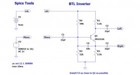
And here's an even simpler one.
Attachments
And here's an even simpler one.
The 2N2222 isn't the best choice in that circuit, a nice high gain transistor would be better at being balanced (assuming matched resistors). Alas a simple transistor circuit introduces some distortion compared to the opamp circuits.
And that C4 bootstrapping cap doesn't do a good job as it loads the input with the output.
The 2N2222 isn't the best choice in that circuit, a nice high gain transistor would be better at being balanced (assuming matched resistors). Alas a simple transistor circuit introduces some distortion compared to the opamp circuits.
I've used that circuit with a variety of transistors over the years and it seems to work well enough.
And that C4 bootstrapping cap doesn't do a good job as it loads the input with the output.
Actually C4 is there to shunt RF off the base-emitter junction to prevent audio rectification. The value is probably a bit high, 47p might be more appropriate.
Ah, that makes more sense, but the 2N2222 base emitter capacitance is perhaps 30pF already. 1nF maybe? Less likely to cause problems to the stage driving this.
Couple of more questions:
Will i have some phase issues by putting new/different amps in? ( i am a noob, remember reading somewhere that all the amps change phase)
In the first schema, is it so that i get full signal before crossover from the IC pin1 (to j2 - 1) .. so pin 1 + ground -?
I have 10 pcs of these plate boards broken, so i could make stereo amps, using input&power from the broken boards
Ah, that makes more sense, but the 2N2222 base emitter capacitance is perhaps 30pF already. 1nF maybe? Less likely to cause problems to the stage driving this.
Yep. Good point. Thanks.
I've been using the 2N2222 a lot lately because I have a bag of 100 of them to work my way through.
Last edited:
- Home
- Amplifiers
- Solid State
- Understanding schemantics