Hi Pete,
It is not that complex, it was actually designed to be simple. I lumped the protection ckts in with the OPS, so that took up a lot more room. Bob's proto, as described in the 2nd edition, uses a separate protection ckt and we are thinking of separating the two. For one it makes the OPS much smaller, so it would fit on a standard HS, two, having a separate protection ckt, can be used for other designs/configs.
PM me if you are interested.
Rick
I wonder how few changes you can make to a universal tiger or plastic tiger (the worst ones I heard) to make a reliable amp out of one? Can the original PCB be patched?
I think that the Bryston is proof that something similar can be made to be reliable
as they do not have any reputation for blowing up. The dual diff front end is not
important but the output stage and compensation is. The Bryston compensation
is not exactly straight forward, lol!
In the department of the non-obvious, the bryston 2bsst that I downloaded has in the feedback line COUT 100n, series a CF1 100p, parallel a box labeled RF1 which is a 14K30. What is RF1, a 14300 henry inductor? that would weigh about 300 lb I believe. Who makes up these new part nomenclatures, the standards committee of Shazamistan? I'd guess Borat is head of the committee.
BTW the QSC 1802 schematic has a bunch of op amps in the front end, looking nothing like a simplet univeral tiger or plastic tiger IMHO.
BTW the QSC 1802 schematic has a bunch of op amps in the front end, looking nothing like a simplet univeral tiger or plastic tiger IMHO.
Last edited:
The QSC PLX is a Tiger type output stage with a gain of about 15, driven directly by a 5532 op amp. They are quite stable and don’t suffer from common mode conduction even under extreme clipping The driver stage is a cascode (just due to the voltage) and the output a darlington with a baker clamp. There is also current limiting for both sub-stages. The overall frequency compensation scheme is also well thought out. Similar modifications to the Tiger would make it stable and reliable. They just tried to get away too cheap and too simple. If you don’t upset it, it works. But it is easy to upset. If you want as cheap and as simple as possible, you want a full complementary EF2 output stage because those are just plain foolproof if you bother to put in the emitter resistors.
....eserviceinfo is requiring I install a missing driver for windows 7,8,10. I don't use windows, I use lubuntu 14 flavor linux. So I can't download from eserviceinfo anymore I suppose.
???
Just downloading from eServiceinfo should NOT need any "drivers"! Only something to accept a PDF file.
I ran Xubuntu (in emulation). The download went fine. Do NOT click on the box in my attached image! That's some kind of spam/scam. As the small print says, the download auto-starts after a *delay*. When that happened, Xubuntu asked to "Open in Doc Viewer?" (I forget the exact name, but its all-purpose reader), I said "OK!", and I saw the manual.
Attachments

There is a lot there in the QSC amps but I'm slowly digging through it.
The output stage feedback is a bit odd with it being AC coupled so C27 is a high
frequency path, not DC. Referring to this schematic, page 62 in the .pdf:
http://bee.mif.pg.gda.pl/ciasteczkowypotwor/SM_scena/QSC/QSC_PLX_Series_Service_Manual.pdf
The output stage feedback is a bit odd with it being AC coupled so C27 is a high
frequency path, not DC. Referring to this schematic, page 62 in the .pdf:
http://bee.mif.pg.gda.pl/ciasteczkowypotwor/SM_scena/QSC/QSC_PLX_Series_Service_Manual.pdf
Thanks for scam identifying.
So on page 63 of the QSC link, is D13 & D16 the baker clamp? Along with D12 & D14 in the base lines?
Per wg-ski in post 24, my working Peavey amps are EF doubles, with emitter resistors. As is my AX6 I think.
So on page 63 of the QSC link, is D13 & D16 the baker clamp? Along with D12 & D14 in the base lines?
Per wg-ski in post 24, my working Peavey amps are EF doubles, with emitter resistors. As is my AX6 I think.
Last edited:
> Thanks for scam identifying.
Interestingly, I saw that box yesterday, but it isn't there today.
It was likely some kind of ad. After all that site costs money to host. However it was an ad that seemed to be "what you want". (It wasn't.) Apparently the site-owner blocked that ad.
The offer to "install drivers" is a classic way to infest Windows machines. Win-users should NEVER do this from strange sites. If you really need a driver, get it from the Reputable Source. And of course Win-drivers do YOU no good, running Linux (a few exceptions where Linux can wrap a Win driver and use it; but not unwanted drivers from unclear sources; the Ubuntu Repository should be your source).
Thanks for scam identifying.
So on page 63 of the QSC link, is D13 & D16 the baker clamp? Along with D12 & D14 in the base lines?
Per wg-ski in post 24, my working Peavey amps are EF doubles, with emitter resistors. As is my AX6 I think.
I think you are right about those diodes but the page shows as 62 in my browser.
About cross conduction in CFP amps, you can add a small cap (~1n) between the bases of the output transistors (NPN to PNP) that will cross couple the two driver outputs. Of course there may be a power supply noise issue but it seems to cancel out, mostly. It's not that much when you consider that big BJT can have a Ccb just as big.
I have also played with "active base resistors" aka Miller cancellation circuits that seem to work but can be tricky/ unstable.
I have also played with "active base resistors" aka Miller cancellation circuits that seem to work but can be tricky/ unstable.
I scratch built a Universal Tiger many years ago and it's been very reliable. IMO, the factory layout was one reason they worked. When I changed the layout I had nothing but oscillation problems until I rebuilt it, though I didn't follow the original layout. One thing that's important is the value of the output inductor. I don't think most people get it right and if it's wrong you can expect trouble.
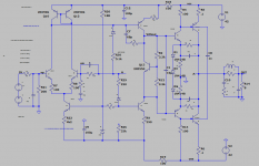
I can go on fiddling with this forever but I want to share some ideas before too much time passes. Note that I got the clipping up over +/-40V by fine tuning the clamping. The diodes between driver emitters can go very wrong if there is too much VAS current so the second circuit has a VAS current limit.
Attachments
CFPs with unity gain give less trouble because the output transistor can only be slightly overdriven, and the driver cannot be overdriven at all. In a CFP with gain, both can be severely overdriven, and will be because the feedback will attempt to correct clipping by driving the VAS harder and harder. Unless steps are taken to prevent that from happening. A big transistor such as an MJ802 is slow as molasses when driven with a forced beta of say 10. Much quicker if you don’t have to pull them out of saturation. And all that charge has to be pulled out by the drivers, which will heat them up too if you’re doing it at 500kHz (in response to an oscillation).
But then again, one of the ‘advantages’ of the Tiger is the fact that the output stage may be driven within one vbe of the rail. All that goes away when modified to keep the output stage out of saturation. Designs like this are iffy at high power. When limited to say 30 volts rail to rail you can use small enough transistors that oscillation and cross conduction can be avoided or at least minimized.
But then again, one of the ‘advantages’ of the Tiger is the fact that the output stage may be driven within one vbe of the rail. All that goes away when modified to keep the output stage out of saturation. Designs like this are iffy at high power. When limited to say 30 volts rail to rail you can use small enough transistors that oscillation and cross conduction can be avoided or at least minimized.
Thus in addition to mods in post 32, I propose the input of the tiger be clamped so it can't be overdriven. The base tiger schematic has 2 1k resistors between RCA jack & the input transistor bases. After those input resistors, back to back 1.8 v zeners or triple stacked 1n4148 connected to signal ground should keep the input transistor bases from exceeding 1.8 v plus or minus.In a CFP with gain, both can be severely overdriven, and will be because the feedback will attempt to correct clipping by driving the VAS harder and harder. Unless steps are taken to prevent that from happening.
Thus in addition to mods in post 32, I propose the input of the tiger be clamped so it can't be overdriven. The base tiger schematic has 2 1k resistors between RCA jack & the input transistor bases. After those input resistors, back to back 1.8 v zeners or triple stacked 1n4148 connected to signal ground should keep the input transistor bases from exceeding 1.8 v plus or minus.
I'm not sure you can buy a 1.8V Zenner but a bridge and one 1n4148 would save a diode, 5 vs 6.
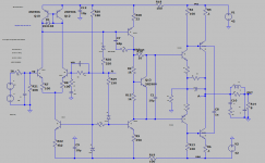
An interesting "minimal mod" 3 part option: I lied about the cross-coupler cap, it has to be ~100n. This makes no effort to clamp the output but instead just pulls the OPs off with the cross-coupling. The driver Vbe is clamped with diodes which also "improves" the driver current peak.
Attachments
CFPs with unity gain give less trouble because the output transistor can only be slightly overdriven, and the driver cannot be overdriven at all. In a CFP with gain, both can be severely overdriven, and will be because the feedback will attempt to correct clipping by driving the VAS harder and harder. Unless steps are taken to prevent that from happening. A big transistor such as an MJ802 is slow as molasses when driven with a forced beta of say 10. Much quicker if you don’t have to pull them out of saturation. And all that charge has to be pulled out by the drivers, which will heat them up too if you’re doing it at 500kHz (in response to an oscillation).
But then again, one of the ‘advantages’ of the Tiger is the fact that the output stage may be driven within one vbe of the rail. All that goes away when modified to keep the output stage out of saturation. Designs like this are iffy at high power. When limited to say 30 volts rail to rail you can use small enough transistors that oscillation and cross conduction can be avoided or at least minimized.
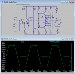
I noticed the advantage of going very close to the rail years ago when testing them on the
bench and had mostly the same thoughts when observing the rail sticking in simulation.
Seems to me that by starting with this design we can choose how far into saturation that
we allow them to go and still have the advantage of less swing required from the front end,
or allowing a cascode without a higher rail voltage.
All good points that you make.
I had intended for this thread to be mostly a pictures thread and I'd like to suggest that if
anyone mods the design that they start a new thread with a clear title of the intent of
their mods. I really dislike threads that wander all over the place and then make it difficult
to find the good info.
Let's not forget the reverse Vbe problem that we discuss in the simulation thread.
anyone mods the design that they start a new thread with a clear title of the intent of
their mods. I really dislike threads that wander all over the place and then make it difficult
to find the good info.
Let's not forget the reverse Vbe problem that we discuss in the simulation thread.
Last edited:
CFPs with unity gain give less trouble because the output transistor can only be slightly overdriven, and the driver cannot be overdriven at all. In a CFP with gain, both can be severely overdriven, and will be because the feedback will attempt to correct clipping by driving the VAS harder and harder. Unless steps are taken to prevent that from happening.
You say that both the driver and output can be severely overdriven which is true but at least
it is only the output that goes into saturation. The driver's collector is one diode drop (Vbe
junction) below the rail and the emitter is at about 1/2 of the output voltage so it cannot go
into saturation which is a good thing. The second transistor in a Darlington connection does
not go into deep saturation because the first transistor limits the drive and that is a good
reason to move to Darlington types for the output devices as was done in the Bryston and
Tiger .01. Something should be done to limit the drive to the first transistor in the Darlington,
a resistor in the drive path is sometimes used.
Both output and driver can be driven into saturation because the base can be driven above the collector. In a normal EF2 or CFP. with unity gain the VAS can’t generate more than the rail voltage. The CFP-with-gain can be fully driven with less than the power supply voltage. It is both its advantage and its weakness.
If the output were replaced by a darlington, the 2nd transistor in the darlington pair can’t be driven to saturation because it is an emitter follower for the first. The first can be a smaller high speed device which can more easily deal with coming out of saturation. Then the first half of the CFP-with -gain could then be an even faster device because the demands on it are less. So even if rail sticking occurs it won’t stick nearly as long, and won’t be as destructive. Clamp both stages, and even that won’t happen.
If the output were replaced by a darlington, the 2nd transistor in the darlington pair can’t be driven to saturation because it is an emitter follower for the first. The first can be a smaller high speed device which can more easily deal with coming out of saturation. Then the first half of the CFP-with -gain could then be an even faster device because the demands on it are less. So even if rail sticking occurs it won’t stick nearly as long, and won’t be as destructive. Clamp both stages, and even that won’t happen.
- Home
- Amplifiers
- Solid State
- Tiger Amp Madness!