Hello to all 🙂
I will try to keep this post with max information. So, I would like to change op amp in Yamaha amplifier.
Yamaha amplifier details: Yamaha AX-10 - Manual - Stereo Integrated Amplifier - HiFi Engine
Service manual with schematics: AX-10.pdf
The CD input has two NJM2068DD
Datasheet: https://cz.mouser.com/datasheet/2/294/NJM2068_E-364244.pdf
After research I would like to try two op amps.
First op amp: LME49720
Datasheet: http://www.ti.com/lit/ds/symlink/lme49720.pdf
Second op amp: LM4562
Datasheet: http://www.ti.com/lit/ds/symlink/lm4562.pdf
The QUESTION is:
May I just simply remove NJM2068DD and place there new op amp? I did reading and checking and I noticed I should solder correct value resistor to avoid oscilation.
So what resistor R270/R271 from Yamaha scheme should be there when I use LME49720 and after trying what R should be used for LM4562 please?

All what I want is much better op amp. But as we know, it's not that easy. Or is it?
Thank you VERY much!
Milan
I will try to keep this post with max information. So, I would like to change op amp in Yamaha amplifier.
Yamaha amplifier details: Yamaha AX-10 - Manual - Stereo Integrated Amplifier - HiFi Engine
Service manual with schematics: AX-10.pdf
The CD input has two NJM2068DD
Datasheet: https://cz.mouser.com/datasheet/2/294/NJM2068_E-364244.pdf
After research I would like to try two op amps.
First op amp: LME49720
Datasheet: http://www.ti.com/lit/ds/symlink/lme49720.pdf
Second op amp: LM4562
Datasheet: http://www.ti.com/lit/ds/symlink/lm4562.pdf
The QUESTION is:
May I just simply remove NJM2068DD
and place there new op amp? I did reading and checking and I noticed I should solder correct value resistor to avoid oscilation. So what resistor R270/R271 from Yamaha scheme should be there when I use LME49720 and after trying what R should be used for LM4562 please?
All what I want is much better op amp. But as we know, it's not that easy. Or is it?
Thank you VERY much!
Milan
The op amp with the values shown has a gain of 3, (R217 + R273/R273).
There is not enough gain to cause oscillations.
I wonder what you expect will happen and don't you think Yamaha may have considered other ICs in the design but plumped with the 2068, a very respectable IC.
Replacing the 2068 with either of your choice is a drop in replacement, similar pinout.
There is not enough gain to cause oscillations.
I wonder what you expect will happen and don't you think Yamaha may have considered other ICs in the design but plumped with the 2068, a very respectable IC.
Replacing the 2068 with either of your choice is a drop in replacement, similar pinout.
Last edited:
@JonSnellElectronic The amp is 20 years old, so I think it would be nice to have little upgrade. I did recap already. But I think the sound could have more detailed heights. I am expecting little sound improvement. I think the op amp should change the sound "colour" so I might to fall in live with this change. 🙂
The gain is actually 3.2 and for each stage is calculated as (2k2/1k) + 1 which is 3.2.
It is very unusual to see two stages in parallel like this, one side feeding what seems to be just the 'record out' feed while the other main output is the two stages resistively summed together, maybe in some attempt to reduce the noise floor.
If you really want to change the 'colour' then try a TL072 as an experiment.
When I checked datasheets, it look like best adepts are:
1. AD826
2. LM4562/LME49720
3. place: TL072

What I know now is no osculations will happen. That's cool! Or should I be aware of some detail on the board above?
1. AD826
2. LM4562/LME49720
3. place: TL072
What I know now is no osculations will happen. That's cool! Or should I be aware of some detail on the board above?
How do you know no oscillations will happen?
Swapping Op-Amps... you have checked to see it's stable haven't you ?
Swapping Op-Amps... you have checked to see it's stable haven't you ?
How do you know no oscillations will happen?
Swapping Op-Amps... you have checked to see it's stable haven't you ?
JonSnell Electronic said:
The op amp with the values shown has a gain of 3, (R217 + R273/R273).
There is not enough gain to cause oscillations.
🙂 The gain is (R271 + R273)/R273 which is a voltage gain of 3.2
Op Amp Gain Calculator
Many stability problems come from having to low a gain rather than to high a gain. Increase the gain and the stability margins improve. The 2068 opamp is classed as unity gain stable which means it is stable for gains down to 1.
Your 2068 stage is a basic gain stage and I actually wouldn't envisage stability issues in practice for this circuit when using 'normal' opamps designed for audio (and general purpose use). The AD826 is an extremely fast and wideband device and that in itself may cause issues when using it in a PCB designed for much slower devices. The only way to know would be to put a scope on it and look.
🙂 The gain is (R271 + R273)/R273 which is a voltage gain of 3.2
Op Amp Gain Calculator
Many stability problems come from having to low a gain rather than to high a gain. Increase the gain and the stability margins improve. The 2068 opamp is classed as unity gain stable which means it is stable for gains down to 1.
Your 2068 stage is a basic gain stage and I actually wouldn't envisage stability issues in practice for this circuit when using 'normal' opamps designed for audio (and general purpose use). The AD826 is an extremely fast and wideband device and that in itself may cause issues when using it in a PCB designed for much slower devices. The only way to know would be to put a scope on it and look.
I am getting be more educated now! Thank you 🙂
Thant calculator looks very helpful, so basically... if I will keep input resistor the same, I will calculate only the feedback resistor and use the right one and everything should be ok, Am I correct? 😕
🙂 The gain is (R271 + R273)/R273 which is a voltage gain of 3.2
Even I've missed a bit off now 🙂
The gain is (R271 + R273)/R273 plus 1
So it is (2200+1000)/1000 plus 1 which is 3.2
Even I've missed a bit off now 🙂
The gain is (R271 + R273)/R273 plus 1
So it is (2200+1000)/1000 plus 1 which is 3.2
So I was looking on op amps specs. Nowhere is "Voltage Gain". Do you have another calculator which will calculate it for some specs? 😀
I am getting be more educated now! Thank you 🙂
Thant calculator looks very helpful, so basically... if I will keep input resistor the same, I will calculate only the feedback resistor and use the right one and everything should be ok, Am I correct? 😕
You can alter either resistor within limits to get the gain you want.
If you are using bjt opamps (like the 2068 or 4562) then DC offset becomes something to consider because an offset will occur due to the unequal input bias voltage developed at the opamp inputs, this voltage being cause by the internal bias current flowing out of the input pins and into the resistors.
If the resistance is not equal then a voltage difference occurs and that difference will be amplifier by the gain of the circuit.
So if you want to use bjt devices then you should use ones with low input bias currents (such as the 4562). The TL072 being FET doesn;t have this issue.
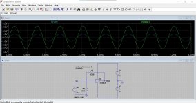
This shows the gain of your circuit, 1 volt peak applied to the input and 3.2 volts peak at the output.
Attachments
So I was looking on op amps specs. Nowhere is "Voltage Gain". Do you have another calculator which will calculate it for some specs? 😀
The raw voltage gain (or open loop gain) of all the opamps we are talking about is massive, so massive that even 1 millivolt of signal would give many volts of output.
It is the feedback that controls the final gain and makes the result independent of the opamp used.
So it doesn't matter if your opamp has a basic gain of 500, 5000 or 500,000, you will still see your 3.2 volts coming out of your circuit when you apply 1 volt input.
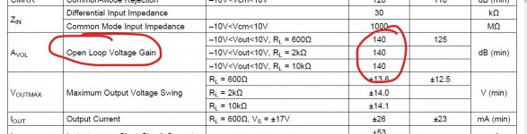
This is the voltage gain of the 4562 from the data sheet. It is around 140db open loop (no feedback) which means a gain of 10 million. It is the feedback that controls the final result though.
Why you don't have a link to Paypal with text "Buy me a beer"?
You know what you are talking about. Would you like to drop me a resistor values for LM4562NA/NOPB, AD826ANZ and TL072BCP and I will buy you a several beers (or coffees)? 😀
Thanks 🙂
The resistor values that are fitted will be fine for the LM4562, the OPA2134 and the TL072. I've never used the AD826 and so I would say that if you try that one then you should really use a scope to make sure it really is stable.
Why not fit a couple of sockets and give them all a try and decide for yourself whether you like what you hear.
Are you sure you want to bother with the old TL072? It has rather poor common-mode linearity, and in term of feedback resistor values you're looking at 10k/4k7 at the very least if you do not want to annoy its output stage overly much, perhaps even 22k/10k. (At this point it can't hurt to have maybe 10 pF in parallel with the feedback resistor, to eliminate input capacitance related gain peaking.) On the pro side, you can quite easily stack two to offset their pathetic driving abilities, or more - mind you, their input capacitance adds up as well.
AD826 is usually depicted with 1k in feedback but I imagine the existing values should work decently as well. Its linearity in general isn't that spectacular but better than the TL072 in common mode at least. (It's a video opamp, so rather designed to drive ~1 Vrms into 75 ohms than 6 Vrms into a few kOhms.) I wouldn't try keeping my finger on this guy though, it'll be at around 400 mW in idle.
With LM4562/LME49720, I'd just leave resistor values as-is, they should work fine.
Really, the input amp as-is isn't bad. I may be inclined to go up to 6k8/2k2 for reduced output stage loading at worst-case levels, but that's about it. Yamaha has done much worse, like torturing a poor little OP275 with 390R/220R at the same spot in the A-S700 (hint: it's an OK-ish load driver but well short of an NE5532). If you don't bother its output stage too much, the NJM2068 isn't a bad performer at all (NwAvGuy measurements - Samuel Groner unfortunately skipped this part).
The question though is, do you even need or want 9.2 dB of gain there in this day and age? CD levels have gone up quite a bit since the early days, and 150 mV of input sensitivity on a CD input quite arguably was generous even when this amp was new. (Where do you typically have the volume pot set, 9 o'clock or even lower?) So if you are running a standalone CD player into this and predominantly listen to releases from the '90s and newer, you might as well take out the 2k2s, replace them with the 1ks (the part even is commonly used with direct feedback) and call it a day. The NJM2068 makes a perfectly fine unity gain buffer at 2 Vrms.
Now if you are running substantially less than CD player level into it, e.g. because you have a modern 24-bit DAC with more than enough dynamic range and you like to have your collection ReplayGained with settings adequate to cover just about everything that has ever come out on CD (like me with an extra -3.2 dB, which means a total of -9 to -13 dB on modern pop releases more often than not)... then you pretty much have no reason to even be bothering with this modding business at all. As NwAvGuy showed, the NJM2068 will happily work in a gain of 3 circuit with 1k5/750R at 2 Vrms all day long with negligible distortion, and that's a somewhat heavier load than what you have there.
But people just like tinkering, I guess.
In this day and age, I would consider "CD input" a bit of a misnomer... it makes a splendid choice for a computer or mobile player though.
Last edited:
Thanks 🙂
The resistor values that are fitted will be fine for the LM4562, the OPA2134 and the TL072. I've never used the AD826 and so I would say that if you try that one then you should really use a scope to make sure it really is stable.
Why not fit a couple of sockets and give them all a try and decide for yourself whether you like what you hear.
But I still think that some people should have here PayPal link. 😎
I am good with making websites, experienced with soldering, good photographer, but when words like GAIN or OFFSET will appear, I will get frustrated why I didn't study different school. I bought little oscilloscope, so I will read how to use it

- Home
- Amplifiers
- Solid State
- Replacing NJM2068DD in Yamaha Amplifier