I haven't used this for some time and at the moment don't have a specific example to refer to.
However I did have issues on many occasions, for examples...
As I understand the Tian probe, it shouldn't matter exactly where it's placed, ...but it's not always so obvious...where to insert that probe?
And an other example with nested loops,..based on Cherry's concept.
I have used the Tian probe on Cherry style and nested loop amplifiers without problems. So I suspect the real issue is either incorrect probe use, or that the amp doesn't actually behave as you expect and so it looks incorrect to you even when the probe works fine. I have seen results that initially looked mistaken but eventually I realised the reasons why. I have posted a few tools to use a Tian probe with a balanced amp, and to run multiple Tian probes, which makes multi-loop or nested amps easier to understand. Check my posts for the link. Sometimes multi-loop amps do show phase behavior that looks anomalous. Not sure if this is a real error or just my own failure to understand. If you ever have a documented example of this then I would be keen to see it.
What I'd like is...
[Use] the MEAS statement...
Yes, exactly. I think Damir has some examples in his posts [user-id is Dadod].
Best wishes David
Last edited:
I'll have to remember to post something next time I do something on such designs and I have issues.
Damir is one of the experts around the forum, so of course he can inspire others, less experienced. 🙂
I was just working on something and since this topic came up, I added a tian probe to it and tried it out. It seems to be giving consistent numbers, as far as I can tell.
Since examples are the best thing to help better understand things, I'll share what I found in this sim (attached).
If this is right, the phase margin on this design would be almost 51deg, and gain margin more than 5db.
Now there is something that basically nobody talks about when it comes to phase/gain margins: it's not always absolutely necessary to have such and such amount of margins, when we actually know for sure what the load will be on an amp.
Of course when we design an amp to be used for whatever load that can be thrown at it, we aim for more than enough margins to handle the worst loads that could be encountered. But when we do know for sure, exactly what type of load the amp will face, we can compromise for what is sufficient for that load, and no need to aim for much more than that is actually needed.
Case in point: If my power amp will only be used for what would be similar to a sub, which in my case would be the lowest channel in a 4way multi-amp system, and I do know it's only going to be a big woofer with beefy very short cables between that and the amp, then there is no reason to seek huge amount of margins and make sure it can handle hugely capacitive reactance, as that situation will never be encountered. And there can't be much capacitance with a big woofer with beefy short cables.
Now if we're designing for a high channel and the tweeters will be something like a piezo, or maybe electrostatic, or even a ribbon type speaker or something like that, it changes everything...
Does it look like I'm getting expected readings on my current sim?
Attachments
...it's not always absolutely necessary to have ...when we actually know for sure what the load will be
Even if we know the load perfectly we still need certain PM and GM to ensure the system is well behaved.
Time domain is the most obvious, insufficient PM and/or GM will cause transient overshoot etc.
Then we need extra for component and load tolerances.
Case in point: If my power amp will only be used for what would be similar to a sub
The stability is determined near the loop crossover frequency so woofer or tweeter hardly matters, mainly capacitance load from cables or whatever.
A decent Zobel should handle this anyway.
Does it look like...expected?
I would need to see the Tian plot.
There's more to it than PM and GM numbers, even if they are usually adequate to provide a reasonable estimate.
Best wishes
David
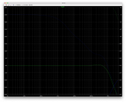
Is there something else besides the V(out) to plot?
With the stepped sim, it plots 2 curves, but they're both V(out). Then we can add cursors and seek those critical crossing points, but I'm not sure my current plot would allow this (attached)
I think the scales might require adjustments to show enough of it to find those critical crossing spots...
One other thing, when we're not dealing with a power amp, what's the use for a bunch of margin anyway? For example if we're looking at a DOA, which would only have for a load a power amp's input. In such case there is no need for a lot of headroom.
And also when it comes to a big woofer loading a power amp, knowing there is hardly any capacitance, even with cables, which would be very short, the only reactance present would be inductive, so the goal is to make that amp stable on inductive reactance, not so much capacitive..
Attachments
Sometimes it's more useful/easier to plot impedance as a function of frequency. It's easy to identify the impedance peak by loading the device with a current source I1, with AC=1.
Zout = Vout/I(I1). Phase margin can be calculated from group delay which can be selected on the right Y-axis.
Zout = Vout/I(I1). Phase margin can be calculated from group delay which can be selected on the right Y-axis.
...besides the V(out) to plot?
With the stepped sim, it plots 2 curves, but they're both V(out). Then we can add cursors and seek those critical crossing points, but I'm not sure my current plot would allow this (attached)...
I think you have misunderstood how the Tian probe works. It should be used as in the example >Here< There are other examples in the thread but they use multiple Tian probes so not so clear until you understand the basic probe.
Best wishes David
Sometimes it's more useful/easier to plot impedance as a function of frequency...
I like to look at impedance too, but I see Return Ratio as crucial. I have never really studied if impedance can mislead you, Dr Ed Cherry did some papers on how the output impedance is related to the Return Ratio. It wasn't as simple as usually presented but I don't remember the details.
Best wishes avid
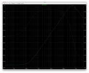
Ok, let's try to take a practical example and look at that impedance peak.
If I get this right, we need to basically short the input, and load the output with a current source and do the .ac analysis on that, plotting that V(out)/I(I1).
So, if I use this in the sim:
Vin in+ 0 0
I1 out 0 AC 1
.ac oct 10 2 10meg
This will short that input and add the current source. Then I get this plot (attached) from that .ac analysis. We get that peak, but then what do we actually look for exactly? Will this provide an actual value for the margins as well as a Tian probe? There is nothing like actual practical examples to learn how to do things.
Attachments
Ok, let's try to take a practical example and look at that impedance peak.
If I get this right, we need to basically short the input, and load the output with a current source and do the .ac analysis on that, plotting that V(out)/I(I1).
So, if I use this in the sim:
.
Post the LTSpice *.asc file and I will demonstrate.
Basically, the Erickson/Masimovic approximation:
Q= Pi * Frequency * Group Delay
Phase Margin = 50.363 * Q^-0.907
I believe that Group Delay is given on the phase (right hand) axis if you select it -- or you can measure it by calculating at the -3dB points.
I was awaiting feedback on that sim I posted a while ago...
Anyway, I dug out an other sim I haven't touched for some time and that one has a nested compensation loop similar to output inclusive, something kind of like TMC I guess, which works quite nicely it seems.
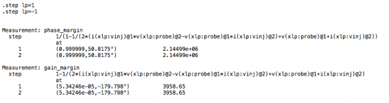
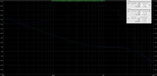
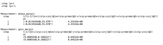
The values returned by the .meas functions are in agreement with what I'm reading off the plot with the cursors.
Seems this amp would have nearly 10db of gain margin and almost 56degrees of phase margin.
Now the question is: Did I do this right? Am I reading the info properly, and placing cursors right?
I placed the loop probe ignoring the inner loop, only to be in the outer one. Is this right?
Also while at it, I'm having an other totally different issue found in this sim, with the power outputs, which are darlingtons, as subcircuits, which works and the plotting of info such as power is also working, but when I use the same exact expression as in the plot, put into a data label, it's not working. Why?
Everything else in data labels work, currents, power, whatever, but not when it's for a subcircuit, even though the same expression works fine in the plot.
And by the way: What would be considered a minimum for gain/phase margins?
Anyway, I dug out an other sim I haven't touched for some time and that one has a nested compensation loop similar to output inclusive, something kind of like TMC I guess, which works quite nicely it seems.
The values returned by the .meas functions are in agreement with what I'm reading off the plot with the cursors.
Seems this amp would have nearly 10db of gain margin and almost 56degrees of phase margin.
Now the question is: Did I do this right? Am I reading the info properly, and placing cursors right?
I placed the loop probe ignoring the inner loop, only to be in the outer one. Is this right?
Also while at it, I'm having an other totally different issue found in this sim, with the power outputs, which are darlingtons, as subcircuits, which works and the plotting of info such as power is also working, but when I use the same exact expression as in the plot, put into a data label, it's not working. Why?
Everything else in data labels work, currents, power, whatever, but not when it's for a subcircuit, even though the same expression works fine in the plot.
And by the way: What would be considered a minimum for gain/phase margins?
Attachments
It looks impossible to tell from what you have shown in the picture. Just do it the standard way, with standard identifiers, like the link I included earlier. Then I can help. If the plot is in fact correct then it looks badly sub-optimal.Now the question is...
Best wishes
David
It looks impossible to tell from what you have shown in the picture. Just do it the standard way, with standard identifiers, like the link I included earlier. Then I can help. If the plot is in fact correct then it looks badly sub-optimal.
Then I don't understand what you mean. This is done with a Tian probe, and I don't know what you mean by "standard identifiers".
And what IS optimal then?
What's wrong with this example?
Are the amounts of margins not good enough or is it something else?
I would think that when we know what the load will be for an amp, and we know the type of reactance and how much it can be, we can dispense with some of the extreme possibilities that an amp could encounter.
Then I don't understand what you mean. This is done with a Tian probe, and I don't know what you mean by "standard identifiers".
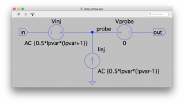
Here is an example.
The Tian probe sources are shown, have standard names, the current source is Ii, potential is Vi, the injection point is called "x" and so on.
So the Tian probe is plotted with a standard reference on the plot pane on the R. hand side.
If you don't show what you have done I can't help, if you invent your own identifiers and expressions then anyone will have to work them all out and I suspect very few people will bother, if any.
Best wishes
David

The Tian probe sources are shown, have standard names, the current source is Ii, potential is Vi, the injection point is called "x" and so on.
So the Tian probe is plotted with a standard reference on the plot pane on the R. hand side.
If you don't show what you have done I can't help, if you invent your own identifiers and expressions then anyone will have to work them all out and I suspect very few people will bother, if any.
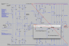
Ok, I think I see what you're looking for.
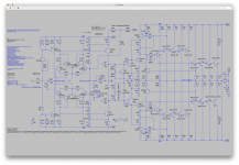
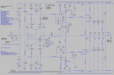
That example is somewhat different because the tian probe is all there visible, unlike mine that was just shown as a small rectangle because the probe stuff is in a subcircuit.
So I'm posting that subcircuit's schematic here, which goes with that previous posting where I also posted the resulting plot.
I didn't make up that probe and my own naming scheme, as this is a widely published tian probe subcircuit. I couldn't come up with this myself.
I wish there was a way to make the cursors more visible on plots, but at least the popup with the numbers gives readable results from the cursors.
Is this what was needed to remove any ambiguity?
Attachments
By the way, on the plot posted earlier with the cursors to read margins, I zoomed in to place cursors more easily, so that's why the x axis only starts at 10khz, and there is no need to see beyond 10mhz..
Is this what was needed...
Spice is poorly structured in some ways - usually in software we want to encapsulate details so they don't confuse us, but in Spice it is easy to have important information hidden in poorly documented and not transparent ways.
The only way to make obvious all the details is to put them all on the top level of the ASC, which is messy.
So there is a bit of a conflict of objectives, for instance-
I don't know if your "in" and "out" of the Tian probe sub-circuit tie to the "in" and "OUT" of the amplifier, this looks incorrect but maybe there is some simple explanation I'm too tired to see.
I don't know what your "OUT" load is, presumably 8 ohms with some capacitance but I can't be sure.
Your power supply is not clear, just "V+" and "V-", presumably with some source impedance but it isn't shown what.
And so on, probably mostly irrelevant but I can't be sure.
Thus Spice's weakness and your circuit implementation combine to make me a bit frustrated.
So just put the Tian probe in exactly as in the example, preferably show me all the details of the input, power supply, load and do the plot.
Also drop the "Method=Gear" option, it's less accurate, shouldn't be required.
Best wishes
David
Spice is poorly structured in some ways - usually in software we want to encapsulate details so they don't confuse us, but in Spice it is easy to have important information hidden in poorly documented and not transparent ways.
The only way to make obvious all the details is to put them all on the top level of the ASC, which is messy.
It's messy and that's why using sub-circuits helps in that regard, especially when a sub-circuit, like the tian probe in this case, is used in many other sims over and over. No need to repeat all its parts, just include it and let it rip..
But overall, LTSpice isn't bad compared to many other options. Some don't even use a GUI at all.
I don't know if your "in" and "out" of the Tian probe sub-circuit tie to the "in" and "OUT" of the amplifier, this looks incorrect but maybe there is some simple explanation I'm too tired to see.
I don't know what your "OUT" load is, presumably 8 ohms with some capacitance but I can't be sure.
Your power supply is not clear, just "V+" and "V-", presumably with some source impedance but it isn't shown what.
Ok, I see you may not be a frequent LTSpice user, and you're not too familiar with how the sub-circuits work.
The labels used in the schematics in a sub-circuits can have the same names as the schematics in which they're included, but that doesn't mean they're connected and the same.
In this case, the tian probe is defined in the sub-circuit as having an "in" and "out", which are defined as pins, so they can be connected to things on the schematic where that sub-circuit is included, and those do correspond to the same in and out shown on the schematic with its rectangular symbol, but those in and out near the symbol are just visual aids to show which pins are which, and those have nothing to do with the other in and out labels in the main schematic.
So the in and out labels in the main schematic are not the same as those in and out from the tian probe sub-circuit.
I'm pointing out on a screenshot with red annotations, what is connected to what, as well as associating those things you didn't notice are associated, such as the supplies and the load, with the zobel, which is also not visualized but put into text instead.
Attaching again the plot with the cursors. I wish it was easier to change some colors to make the cursors more visible, but they're located where the data says in the popup...
Also drop the "Method=Gear" option, it's less accurate, shouldn't be required.
Ok. It didn't change anything. It's just a bad habit to always add it. My default is modified trap...
Attachments

It's messy and that's why using sub-circuits helps...
But overall, LTSpice isn't bad compared to many other options.
LTspice is excellent, the problem is in the structure of SPICE itself.
The modularisation is not well done and the alternative to a mess is a lack of transparency.
Nice to use sub circuits for one's own work but if you want to post a screen shot they are far from clear.
Ok, I see you may not be a frequent LTSpice user, and you're not too familiar with how the sub-circuits work.
Frequent LTspice user but I don't use sub-circuits much, for the reasons I have already mentioned.
The labels used in the schematics in a sub-circuits can have the same names as the schematics in which they're included, but that doesn't mean they're connected and the same.
Yes, and this will be evident in the ASC - however I am not sure how I can confirm this from a screen shot alone.
And I'm too tired to check if there's a way, it's late in my time zone, more tomorrow.
It's just a bad habit to always add it. My default is modified trap...
Yes, better.
Best wishes
David
Last edited:
I was thinking about gathering the pieces and make a zip with everything in it for that simulation, plus putting the tian probe in the main asc to avoid the sub-circuit.
But this isn't as easy as it seems, with things being pulled in from various other places, and I'd have to rewrite that string to put in the plot to make it work outside of the sub-circuit.
That string alone is a big mess and rather complex, which if I attempt to rewrite, I'm highly likely to screw it up. Then it would be a pain to track down my mistakes.
That tian probe in a sub-circuit has been used by many, posted quite some time ago and widely used, so it's pretty much assumed to be valid and working, hopefully to not have to dissect it before trying to interpret its results.
Even though it's in a sub-circuit, it works just the same as if it wasn't, so why not treat its results the same?
So, assuming the proper string was put in the plot to add the trace(s), the curves would be correct (right?).
Then it's a matter of interpreting this properly.
The measure statements give out numbers, and from what I did with the cursors on the plot, I got the same numbers again, so this seems in agreement.
Now the results getting interpreted is an other story.
From those results I obtained on that test sim, the phase margin would be about 56degrees, and almost 10db of gain margin.
From all the discussions I've read about this stuff, this seems like a pretty darn good amount, of both. And for my own usage, I think it would be far more than actually truly necessary.
If an amp is designed without knowing what loads it might be "exposed" to, we have to give it as much stability margin as possible, to face whatever can be thrown at it, and in many cases, this is way more than would be needed for less demanding loads.
If an amp is going to be for ribbon speakers, or perhaps electrostatic ones, maybe even piezo, then this issue about stability margin can definitely be something to look at. But if the load is known, ahead of time, to be a single simple electrodynamic type, with very short cables, no passive filters or any other such junk in the way, then this should reduce the requirements quite a bit.
Also, it might be a good idea to have an extra zobel added in the speaker box near the speaker itself, which would be at the far end of the speaker cable. This would make it 2 zobels, one at each speaker cable end. That should also play in favor of fighting against ingress of whatever interference might be around.
- Home
- Design & Build
- Software Tools
- Determining Phase and Gain Margins in LTSpice