Hello,
i was given this amplifier from a friend who was an engineer in a TV station.
This was a DIY amplifier built by their old retired service technician built sometime in the late 70's 80's ?
It was used to power a a pair of Rogers 11 ohm LS3/5a in their dubbing studio.
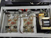
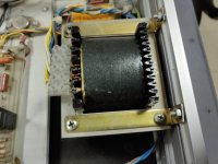
It has XLR balanced in and that possible the role of the Transformers after the inputs (Large silver spheres) ?
Since i am not very familiar with older Amp designs i need your help in identifying this design ,circuit ,
How good is it ?
Is it worth upgrading modding in order to keep ,can you tell its power rating ?
Any tips , help or mods will be greatly appreciated .
Cheers to all
1a.jpg 4a.jpg 6.jpg 8a.jpg 8b.jpg 9 balance switch.jpg 9a.jpg
9c.jpg 10.jpg 12 psw.jpg
i was given this amplifier from a friend who was an engineer in a TV station.
This was a DIY amplifier built by their old retired service technician built sometime in the late 70's 80's ?
It was used to power a a pair of Rogers 11 ohm LS3/5a in their dubbing studio.
It has XLR balanced in and that possible the role of the Transformers after the inputs (Large silver spheres) ?
Since i am not very familiar with older Amp designs i need your help in identifying this design ,circuit ,
How good is it ?
Is it worth upgrading modding in order to keep ,can you tell its power rating ?
Any tips , help or mods will be greatly appreciated .
Cheers to all
1a.jpg 4a.jpg 6.jpg 8a.jpg 8b.jpg 9 balance switch.jpg 9a.jpg
9c.jpg 10.jpg 12 psw.jpg
Attachments
-
 1a.jpg640.2 KB · Views: 302
 -
 4a.jpg520.4 KB · Views: 321
 -
 6.jpg507.6 KB · Views: 317
 -
 8a.jpg581.3 KB · Views: 313
 -
 8b.jpg515.3 KB · Views: 316
 -
 9 balance switch.jpg445 KB · Views: 183
 -
 9a.jpg527 KB · Views: 181
 -
 9c.jpg642.9 KB · Views: 170
 -
 10.jpg432.2 KB · Views: 179
 -
 12 psw.jpg457.9 KB · Views: 183
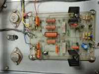
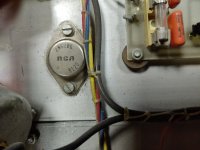
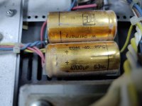
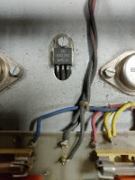
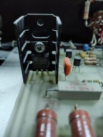
From what I can see at a first glance its pretty standard. The output devices are darlingtons rated at 80V, so the supply is presumably around +/-40V (caps are 63V). Input section looks like some kind of differential pair, but without tracing out the whole circuit its a guess.
Feedback network 27k, 1k2, so gain is x 23.5, again pretty standard. There appears to be a 1k bias-setting pot on the board, connections to Vbe multiplier transistor and output devices are hidden under the board.
It looks nicely made, could easily be a one-off home project, could easily be from a magazine article, the output device part numbers didn't seem to find a circuit in google.
Circuit improvements would probably involve adding quite a lot of stuff (such as current mirror load, more current sources?).
The transistors might be upgradable, for instance lower noise on the inputs, more robust output devices (higher voltage and better operating area).
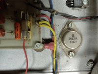
Check the electrolytics as a matter of course, the date codes on the transistors are around 1986's, but one of the output devices is more recent, '91, so must have failed (hence my comment about more robust output devices).
Feedback network 27k, 1k2, so gain is x 23.5, again pretty standard. There appears to be a 1k bias-setting pot on the board, connections to Vbe multiplier transistor and output devices are hidden under the board.
It looks nicely made, could easily be a one-off home project, could easily be from a magazine article, the output device part numbers didn't seem to find a circuit in google.
Circuit improvements would probably involve adding quite a lot of stuff (such as current mirror load, more current sources?).
The transistors might be upgradable, for instance lower noise on the inputs, more robust output devices (higher voltage and better operating area).
Check the electrolytics as a matter of course, the date codes on the transistors are around 1986's, but one of the output devices is more recent, '91, so must have failed (hence my comment about more robust output devices).
Last edited:
Thanks allot for the information,
of course i can remove the boards and look more into detail.
Probably the amp had a malfunction sometime in the 90's and was serviced ,
i was told that it was on 24h for many years ,but was not used very much since it was in a backup dubbing room before the switched to self powered Genelecs.
Of course allot can be changed but the point is if its worth it and if the cost of the spare parts can lead into buying a better quality used one.
I thought that maybe a minor mod ,but then again is the question of sound quality
after all.
DIY is extremely fun but sometimes the cost can be like re-inventing the wheel.LOL
Does it work? If so, enjoy it and worry about upgrades and mods after you live with it long enough to find its flaws.
Strictly a guess but based on the transformer, outputs and Marks assessment of +/-Vdc, I would think it is 30-50 watts at 8 ohms. But perceived volume would depend on gain and pre used with it.
Agree with Mark, it looks to be well made and he certainly took his time constructing the amp.
Strictly a guess but based on the transformer, outputs and Marks assessment of +/-Vdc, I would think it is 30-50 watts at 8 ohms. But perceived volume would depend on gain and pre used with it.
Agree with Mark, it looks to be well made and he certainly took his time constructing the amp.
Well thats a good point!
Yes it works ,only the balance rotary (center) switch needs replacement,
or perhaps ditch all the knobs,volume L R and the balance ones and use a preamp.
Didn't spend time evaluating but sounded at least proper with out pops hiss etc.
Only thought was perhaps change PSU to a toroid perhaps and or recap what can be recapped with better quality ones (Jenzten,clarity etc)and that if results can be heard otherwise,like you said plug and play !!
I wouldn't recommend doing that. Amps like this tend to have a fair amount of gain, maybe 34 dB (about as much as needed for full output at 0 dBu = 0.775 V in), and the input volume control is quite necessary to keep preamp noise at bay and adapt to varying input level (pro levels can be quite high, especially when trying to accommodate long runs - a full +4dBu may translate into +22 dBu peak).Yes it works ,only the balance rotary (center) switch needs replacement,
or perhaps ditch all the knobs,volume L R and the balance ones and use a preamp.
If the problematic switch is not physically broken, taking it apart and cleaning it may be enough to restore it to working operation.
You didn't show the actual XLR input jacks. I would make sure that pin 1 is wired according to AES48-2005 (a recommendation much newer than the amp), which means directly to chassis on the shortest possible path. Running it to signal ground somewhere can seriously degrade input CMRR.
Transformer inputs still find use in hostile environments, as they tend to provide very high CMRR plus actual galvanic isolation, though fidelity may be impacted somewhat, depending om input level and source impedance.
I would be looking at good industrial electrolytics rather than dubious exotica. See what BCComponents, Nichicon, Panasonic and Elna have to offer.Didn't spend time evaluating but sounded at least proper with out pops hiss etc.
Only thought was perhaps change PSU to a toroid perhaps and or recap what can be recapped with better quality ones (Jenzten,clarity etc)and that if results can be heard otherwise,like you said plug and play !!
When recapping, I would consider modifying the amp to accept radial capacitors at least in some spots, like the big power filters... much easier to find and a lot more choice, not to mention less parasitic inductance. Outside of speaker crossovers or tube circuits, axials have pretty much gone extinct.
Last edited:
I find e-form transformers in general have better lightning pop resistance than toroids. That pop you get in the speakers several seconds before the thunder. Also toroids in general need series NTCR on the primary to prevent large surge at turn-on. Perhaps you don't have much lightning in the EU. We certainly do here.Only thought was perhaps change PSU to a toroid perhaps and or recap what can be recapped with better quality ones (Jenzten,clarity etc)and that if results can be heard otherwise,like you said plug and play !!
I'd replace the electrolytics based on the calender, and do something about protecting your speakers if they cost more than $20. Split supply amps can toast speaker drivers or rip the surround if an output transistor fails, and this one has had one OT fail already. Sakis has a lot of bad things to say about durability of darlington output PA amps that come through his shop. A good RJKeene nfet speaker disconnect on DC detect circuit is in order, IMHO. See protection threads.
Checked the bias and offsets?
No i haven't done anything!
These are all good information guys ,thanks.
I would just start with cleaning the balance button or perhaps find a modern replacement.I understand the gain principle.
As far as the rest i will see in industrial electronics what is available ,don't want to spend to much on the thing .
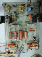
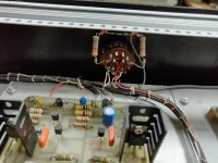
nice old diy amp! Fancy seeing old soviet Russian parts - power resistors and W-Germany (West) el. caps 😀
Look at those big brown power resistors with "МЛТ-2" sign on them. These are the soviet made 2W power rating resistors.
Well yes you are right! Never knew Soviet Era exported electronics to Europe!
West Germany ,Soviet Russia in one kit in the 80's ....thats unique!
West Germany ,Soviet Russia in one kit in the 80's ....thats unique!
i think the output transistors are not changed - both pairs have the same dates ( 82 and 90). could be the beginning of the 1990s, after the fall of the Berlin Wall, soviet details were also freely circulated between DIY amateurs.
Yes you can be right ,i was told that this amp was much older then then 90's maybe not,
The thing is that this amp was made or assembled in Greece!
The thing is that this amp was made or assembled in Greece!
Oh yes but i think the fake electronics thing didn't start much before the China market opened.
Some Soviet transistors and or tubes were pretty good,i knew some guys who bought vintage soviet ham radios and military radios to built tube amps.
Dont know much about solid state parts though.
Some Soviet transistors and or tubes were pretty good,i knew some guys who bought vintage soviet ham radios and military radios to built tube amps.
Dont know much about solid state parts though.
- Home
- Amplifiers
- Solid State
- Help identifying - evaluating old DIY Amplifier