most op-amps do not have distortion modeled. You can often open the model in your simulator and the comments will tell what is modeled. How well any particular spec is modeled is yet another question.
Well, that mainly means that you do have to build a prototype, then measure results and listen to it.
Are simulations of discrete circuits more predictable?
Again, it all depends on the accuracy of the models. One key difference is that with discrete transistors, you're more likely to have some rendition of the transistor's transfer characteristics.
But, step back a second. You should be able to get enough information from the op-amp datasheet to determine what its distortion should be, and for any number of the op-amps mentioned in this thread, it should be 'very small'.
But, step back a second. You should be able to get enough information from the op-amp datasheet to determine what its distortion should be, and for any number of the op-amps mentioned in this thread, it should be 'very small'.
I was hoping someone would find it interesting running the simulations and comment on the findings.
I have several asc files here from sims I did.
I have several asc files here from sims I did.
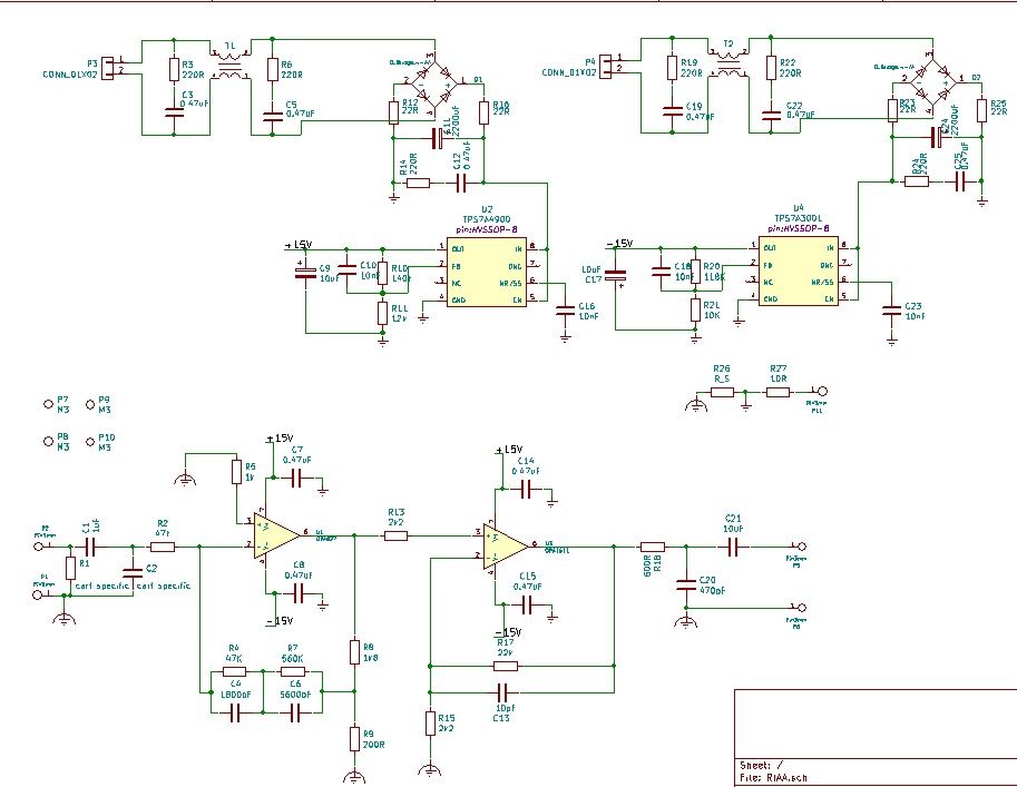
I hacked this up a couple of years ago, sounds fine be a useful starting point as it has most of what you need done. Let me know if you want the kicad files and I will post them up.
 [/URL][/IMG]
 [/URL][/IMG]
Last edited:
Thanks. What were the opamps used on the RIAA?
The only thing I don't like is the input series capacitor. I don't want any cap there.
I will try to run a simulation with it.
The only thing I don't like is the input series capacitor. I don't want any cap there.
I will try to run a simulation with it.
Thanks. What were the opamps used on the RIAA?
The only thing I don't like is the input series capacitor. I don't want any cap there.
I will try to run a simulation with it.
OPA827 and OPA1611 op amps, OPA827 has a very low input offset voltage and as its FET input not a lot of bias current obviously!, so you should be OK leaving the input cap out if you want.
Last edited:
Ah, the very noisy inverting circuit - don't use that, use the non-inverting one without the series 47k resistor (which blows away all hope of low-noise).I hacked this up a couple of years ago, sounds fine be a useful starting point as it has most of what you need done.

Even with a NE5534A the input current noise will be converted to 19nV/sqrt(Hz), combined with the 28nV Johnson noise is 34nV/sqrt(Hz). Can do 15dB better than that...
Last edited:
Most of the noise is the much less objectionable LF, in practice record surface noise dominates.
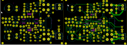
Here is a PDF and the KiCad design files, as I said treat it as a starting point, its not a polished design just "good enough".
Attachments
Last edited:
For phono I would use a balanced design. Only a few more resistors and possibly caps but the result can be quite substantial, especially with MCs but MMs also benefit.
cheers,
cheers,
Yes but there is a balance between no compromise== never finished and very good && completed. It’s a dual mono design with high grade components, op amps, regs and sounds pretty good.
Of course I agree that is better to have a very good & completed project, instead of unfinished no-compromise.
But what would you consider no-compromise version of this one? What would you change or do?
There are "no-compromise" preamp projects, like discrete ones by John Curl, that might be so. But now are impossible to make, because of parts availability.
Can you open an LTSpice file and simulate it?
There's a discrete RIAA preamp, based on an '80s Luxman preamp, that sounds superb and even if I don't think it's a no-compromise project it does sound (in the commercial version that I listened to) outstanding.
Now, the original transistors are not available anymore, so you can't really do a "clone" of it, but what can be tried is using newer available parts and see what you get.
Then I can compare it with the original preamp, which a friend of mine has, and see how close did I get to the original sound.
Now what about better resistors to use on this preamp?
We did intensive tests with my friend with many passive parts, and they do change things. Sorry if that is something many will not agree with, but we didn't imagine those changes. They were there and were repeatable.
Things can get very crazy with resistors prices, if you look at Parts Connexion or HiFi Collective catalogs.
What would anyone recommend as a good compromise between price and audio result?
Of course that the most critical parts are those in the RIAA filter.
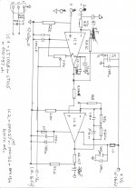
balanced russel
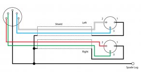
In attachement - just an idea how russel's RIAA could be turned balanced. The other attachement shows XLR to phono (on turntable) connections.
Re resistors - I use Dale resistors in signal path, 1/4W but not less.
cheers,
In attachement - just an idea how russel's RIAA could be turned balanced. The other attachement shows XLR to phono (on turntable) connections.
Re resistors - I use Dale resistors in signal path, 1/4W but not less.
cheers,
Attachments
Last edited:
What is pin 1 of that output XLR connected to? It should be connected to the chassis/case right where it is mounted, but then don't connect that spade lug or you got yourself a nice ground loop.
Jan
Jan
I guess if I wanted to improve it then probably use the latest LT regulators and maybe each op amp gets its own regulated supply, going a bit further maybe a servo on the input op amp, if it was moving to balanced then I would start again. Of course you can play with different components depending on your budget but as I said this was a compromise between it being as good as possible in the time available. One point regarding balanced operation, yes balanced is technically better but if you are very careful with layout, performance of single ended can be very good.
Last edited:
You right Jan. I just attached this diagram from some article on balanced turntable connection without analysing it. The correct version from the Aqvox manual is attached. Cable screen is connected to pin 1 (XLR) and free on the other end, while turntable ground is directly connected to the chassis - not shown on this drawing.
russel - when it comes to phono, balanced inputs are used mainly to eliminate noise picked up by cabling. It's especially applicable when one uses MC cartridge as the noise to signal ratio can be pretty high. When it comes to phono design as such there may be no difference. In this case it's your RIAA phono restructured to use balanced input to eliminate that external noise.
With MC one can use paralleled op-amps or very low noise dual transistors to reduce "circuit" noise.
Of course low noise PS should be used to maximize low noise benefits. That is why some use batteries for PS.
cheers,
Attachments
Last edited:
- Home
- Source & Line
- Analogue Source
- OPA828 for RIAA preamp