I am sorry I do not understand why you are asking this question again. Sources of driver distortion and thus nonlinear Z are well known and described. Please visit Klippel web page and download documents dealing with driver distortion. A small and basic abstract with main sources of nonlinear Z attached.However, where is the non-linear part of the driver Z coming from?
Attachments
.....because the distortion from loudspekers is way too high. Still.
We would like to find New ways to reduce distortion from drivers. Obviously, by Not making them just as they are being made now.
THx-RNMarsh
We would like to find New ways to reduce distortion from drivers. Obviously, by Not making them just as they are being made now.
THx-RNMarsh
Last edited:
In A/B comparisons I find standard ferrite/iron speaker magnet assemblies are noisy.......Goop clarifies the sound of drivers somehow, similarly Goop applied to steel amplifier chassis clarifies sound, ditto iron cored crossover conductors and Class D ferrite output inductors. Barkhausen noise in the iron or in the ferrite or something else, I don't know ?.Are ferrite magnetics better or worse than iron for the center pole piece?
Don't hold your breath Richard, but yeah plenty of us are sick of his automatically seeking to discredit you, JC and anybody else, I expect SPS or father rejection is source of disrespectful behaviour. Syn08, Large BQP works, why don't you just get one and experience for yourself, ?.Is this really necessary? What is your major malfunction and claim to fame such that your opinions like this are useful here or anywhere? Contribute to the subject, pls.
Dan.
Last edited:
Results, yes. Great, never know.I am expecting great results from you JN in this regard.
🙂
-RNM
Metrology is the most important thing. If you want to make something better, you must be able to measure it.
Money no object, I would make the front plate laminated out of .1 or .2mm iron with edm'd radial slits, pole piece edm'd radially as well. Also, mag circuit symmetric to the faceplate so that vc position does not alter coupling between it and the iron.
As to shorting ring lowering inductance...a coil produces magnetic field in a magnetic circuit. When something reacts by producing opposing field in the same circuit, the net total flux is reduced.
Inductance is the relationship between terminal current and total field energy. Anything that reduces the total field reduces inductance.
Jn
What a load of malarkey.Richard, they (coil winder and 8) would rather put us down, that move forward in a useful way. Your experience with LLL is unique, and your overall experience shows this being most useful for audio design. Can't say the same for our critics.
I've defended Richard, as well as you on occasion.
So that schtick isn't working. Nor useful, so stop playing the victim as it doesn't look pretty.
Jn
No. He has claimed Lenz's law is not a law.😕Shooting from the hip here, but it seems to me ETM is referring to the H field in a current drive regime whereas Jneutron is referring to the B field in a voltage drive regime.
He bolsters that argument with an incorrect understanding of transformers.
Jn
In a current drive regime, you have a controlled coil current which is in phase with the H field it generates. The H field potentiates a B field which develops according to the magnetic impedance (or complex permeability) of the flux loop that runs through the coil and shorting ring. At HF the shorting ring dominates the magnetic impedance of the flux loop. As such it experiences a controlled H field drive regime, and responds with a B field. The shorting ring exhibits magnetic inductivity, so the B field lags the H field by 90 degrees. This is the same B field which passes through the voice coil, and the voice coil EMF leads the B field by 90 degrees, resulting in a net phase of zero.
The shorting ring shows magnetic inductivity because the H field generated by the eddy currents leads the B field by 90 degrees. As the ring EMF is the derivative of flux and the ring is resistive, the EMF, current and resulting H field all lead the B field by 90 degrees. Since the H field is the controlled quantity in this case, instead the B field lags the H field by 90 degrees.
So the coil generates a magnetic field in phase with it's current. The shorting ring opposes that field so it lags by 90 degrees, and then the coil EMF leads that field by 90 degrees, resulting in a total zero degrees assuming the shorting ring is resistive.
Last edited:
Contribute to the subject,pls.
Unfortunately I can't without Mr. Lenz. Anyway, I'll first wait for you to contribute more than stirring the pot.
Not sure where to go with that...
Here, I'll loan you one of these..."-"
jn
Much appreciated.
sorry I couldn't make it a small jpg, the pic is 5.2meg
cheers, jn
Ah, a clever expanding mandrel that takes advantage of the taper of the centers. How did you get the super thin metal on the sides? Bandsaw? Slitting saw? Sheet metal and glue?
Here's one for you JN - Cube in a cube.sorry I couldn't make it a small jpg, the pic is 5.2meg
Re measurements, if you remove dustcap/dome you can lock the voice coil former with putty or glue etc without destroying the driver completely. Depending on the glues used you may find you can dismantle your drivers non destructively using solvents and/or heat gun.
Dan.
I used my 5 inch metal bandsaw. Pressed a 1/4 inch pin into a half inch plywood, clamped that in the saw such that the blade centered on the pin, used a physical stop to limit blade just above the pin height. It required cutting each slit twice as the remaining metal is angled. It's about 50 to 75 mils thick at the inner hole.Ah, a clever expanding mandrel that takes advantage of the taper of the centers. How did you get the super thin metal on the sides? Bandsaw? Slitting saw? Sheet metal and glue?
My plan is to cut styrofoam into a conical shape using a hotwire and a rotating platform..I will use both sides of the shaped foam (both innie and outie) and plywood parts to clamp the foam on both sides of the cone. Then, a simple threaded rod type device to actually push and pull the cone to a specific position. The assumption is that it will be strong enough to get locked coil readings with the inductance meter without damaging the cone.Re measurements, if you remove dustcap/dome you can lock the voice coil former with putty or glue etc without destroying the driver completely. Depending on the glues used you may find you can dismantle your drivers non destructively using solvents and/or heat gun.
Dan.
Hopefully it's a good plan.
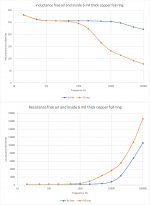
Ran the inductance sweep on the coil and shorting ring. It performed as expected.
Recall, this whole Lenz discussion began when PMA posted an inductive measurement that showed L dropping significantly with frequency. I said that is consistent with a shorted turn, which is exactly what a shorting ring is, especially if it is in close proximity to the voice coil.
Note that the free air readings are pretty solid out to almost 10 Khz, while the shorted ring readings start to go nuts at about 1Khz. Remember, this is a 6 mil thick ring, and it only covers 2/3rds of the inductor because the last four turns of the coil are on the top layer. I would have to peel off 4 turns to put the ring entirely over the coil body, but do not consider it necessary.
Another point of extreme interest...note that the resistance at 10Khz with the ring is 4 ohms. That is dissipation within the ring. That dissipation is communicated to the ring by the flux, so a co-wound coil (tap coil) will see that flux communication. As a consequence, that dissipation information will be part of the tap signal, and subtraction of the tap voltage from the voice coil terminal voltage will remove that dissipative entity from the remainder. That leaves the coil resistance as the difference signal and ignores the ring dissipation.
jn
Attachments
Last edited:
I tried insertion of a 0r22 sense resistor in feedback path of a tube amp simulation using Stereophile speaker load model. THD of speaker current drops from 0.256% to 0.199% at 8Vpp and 1kHz.Its the non-linear impedance of the coil as it moves thru mag field which is a source of distortion corrected by the sense resistor method or current FB...
Last edited:
I tried insertion of a 0r22 sense resistor in feedback path of a tube amp simulation using Stereophile speaker load model. THD of speaker current drops from 0.256% to 0.199% at 8Vpp and 1kHz.
Yes but this from bad to bad. Have you tried any normal amplifier design? Your speaker model had some non-linear components included?
Last edited:
I went through this paper today - last time I designed transformers was for SMPS using a spread sheet back in 1989 when I was young and in full command of my limited intellectual faculties (100 kHz flyback which was fast for the day).
However, back on the ground here in 2019, the relationship between magnetizing current and load current has finally been made clear. As is the fact that the secondary load current does not lag the primary load current component only that it is 180 degrees out of phase with it. It’s the mag current only that lags the source voltage by Pi/2
Thank you for sharing the paper.
Here is the inductor, ring, and foil I used for the test.
The foil is .003 inches by .500 inches. The ring is two turns.
What is really tweaking my interest is the fact that this thin ring caused the resistance of the inductor to rise from .22 ohms to 4 at 1Khz.
If the ring is behind the gap such that excursion towards the back plate brings more ring into play, and towards the front less, that would indicate that the high frequency resistance the amp sees is going to be position dependent. Since the vc resistance is in series with the ring dissipation resistance, this should cause intermod distortion.
jn
Attachments

Last edited:
Here's one for you JN - Cube in a cube.
Re measurements, if you remove dustcap/dome you can lock the voice coil former with putty or glue etc without destroying the driver completely. Depending on the glues used you may find you can dismantle your drivers non destructively using solvents and/or heat gun.
Dan.
How about this- Carved Ivory Puzzle Balls – Wonders of Nature and Artifice
This evening I have been listening to Bernard Haitink conduct his last but one concert. Good going for 90! A recent interview with him was played in the break and listening to him talking about music and musicians and how he conducts you drives home how flat and lifeless stereo reproduction is compared to being there.
No, I not on a normal amp yet. Speaker model is from Real-Life Measurements | Stereophile.comYes but this from bad to bad. Have you tried any normal amplifier design? Your speaker model had some non-linear components included?
Last edited:
Wow - some serious skills their from the Bruns guy and the ancient Chinese stuff as well!
Wow - some serious skills their from the Bruns guy and the ancient Chinese stuff as well!
Funny, I "peeked" where I was not supposed to in China and saw a room with CNC machines turning out jade replicas for tourists (ivory is illegal).
It will be interesting to see what the model looks like should we get a better handle on the nonlinearities.
Jn
- Status
- Not open for further replies.
- Home
- Member Areas
- The Lounge
- John Curl's Blowtorch preamplifier part III