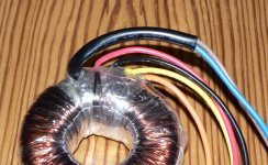
I have a toroidal transformer where the supplier has no wiring information like the one in the schematic pic below. When I asked which wires to wire for the centre tap, I was advised to use the red and orange wires which happens to be the 2 outer wires. The information on the toroidal shows one secondary as black-red and the other orange-yellow.
This tends to go against my past experience where all the other toroidals I remember and have pics of have the end wires (wire 1 red + 4 orange in the pic) going to the bridge rectifier and the middle wires (wire 2 black + 3 yellow in the pic) going to the power supply ground. This is how I have wired it and it works fine.
My question is, can it be wired as suggested using the red and orange outer wires to the power supply ground and is there a standard on toroidals with the sequence of the secondary wires where wire 1 (red in this case) is the winding start and wire 3 (yellow in this case) is the other winding start. Of course it could be in reverse with winding start from the other end orange and black as shown in the schematic.
Attachments
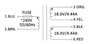
Typically, the secondaries will be wound in a bifilar arrangement.
It won't matter which color wires are connected to ground, only that the two secondaries are in series and in proper phase.🙂
It won't matter which color wires are connected to ground, only that the two secondaries are in series and in proper phase.🙂
as per the drawing if you connect the yel and black together, put a meter on the red and org. if you get 0 VAC replace the yel with the org. You should now get something close to 36 VAC.
My question is, can it be wired as suggested using the red and orange outer wires to the power supply ground and is there a standard on toroidals with the sequence of the secondary wires where wire 1 (red in this case) is the winding start and wire 3 (yellow in this case) is the other winding start. Of course it could be in reverse with winding start from the other end orange and black as shown in the schematic.
Your choice, you can connect together either the red/orange wires for the CT,
or the yellow/black. Either gives the same result.
Last edited:
Thanks for the advice. I get 34VAC no load across the red and orange and +/-23VDC on the output. This is a 15-0-15 transformer.
Thanks for the advice. I get 34VAC no load across the red and orange and +/-23VDC
on the output. This is a 15-0-15 transformer.
Right, when loaded you get 15V x 1.414 = 21VDC, less a diode drop, so about 20VDC.
It's not unusual for a transformer to have a voltage rise of +10% when unloaded.
Last edited:
- Status
- Not open for further replies.