There are already many projects for preamps around but nothing really suiting what I'd like for an incoming project (an integrated amp for a friend). So I've been reading through the ESP website and D. Self small signal book to patch together something.
All opamps will be opa1642, to take advantage of their low power consumption, ability to drive 2K loads and good performances in non-inverting configuration. Impedances across the circuit have mostly been kept in check at about 2K.
For the auxiliary circuits (remote control, input relays, muting, etc), I'll recycle bits of an earlier arduino based project. Everything will be powered from a 5V adapter and the analog section from a DC-DC converter.
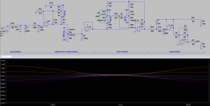
Input section:
This will be duplicated at each input. The 7k5/2k5 divider is for modern sources, at 2Vrms. There will be a switch or jumper to disconnect the 2K5 resistor, for older or weaker sources. No attenuation anymore and higher input impedance. The input selection through relays will take place after this section.
Balance and volume control:
The input buffer has variable gain in order to implement the balance control. The gain with the pot centered is about 9dB.
The volume control is followed by a simple non-inverting buffer due to its highish impedance (the only motor pot easily available is the rk168, mostly found in 100k version). The volume control is put before the tone control section, to minimize risks of clipping.
Tone controls:
Nothing much to say. It's a classic Baxandall circuit, with bass and treble controls.
Output buffer:
This gets me a balanced output that can be useful with class-d amps and restores absolute phase if desired. The first buffer is also a low pass filter to bring back down the HF after the tone controls.
Does this plan seem sound ? Any errors to be found or improvements to suggest ? I'd be grateful to read any comments on this thing before starting the PCB design. 🙂
All opamps will be opa1642, to take advantage of their low power consumption, ability to drive 2K loads and good performances in non-inverting configuration. Impedances across the circuit have mostly been kept in check at about 2K.
For the auxiliary circuits (remote control, input relays, muting, etc), I'll recycle bits of an earlier arduino based project. Everything will be powered from a 5V adapter and the analog section from a DC-DC converter.
Input section:
This will be duplicated at each input. The 7k5/2k5 divider is for modern sources, at 2Vrms. There will be a switch or jumper to disconnect the 2K5 resistor, for older or weaker sources. No attenuation anymore and higher input impedance. The input selection through relays will take place after this section.
Balance and volume control:
The input buffer has variable gain in order to implement the balance control. The gain with the pot centered is about 9dB.
The volume control is followed by a simple non-inverting buffer due to its highish impedance (the only motor pot easily available is the rk168, mostly found in 100k version). The volume control is put before the tone control section, to minimize risks of clipping.
Tone controls:
Nothing much to say. It's a classic Baxandall circuit, with bass and treble controls.
Output buffer:
This gets me a balanced output that can be useful with class-d amps and restores absolute phase if desired. The first buffer is also a low pass filter to bring back down the HF after the tone controls.
Does this plan seem sound ? Any errors to be found or improvements to suggest ? I'd be grateful to read any comments on this thing before starting the PCB design. 🙂
Attachments
When you disconnect R17 the input impedance at AC goes to 477k5 which I find a bit on a high side. Why not target a more conventional input impedance of 47k at all input attenuation settings?
Well, I need one divider at the input to accommodate DAC, CD or pro gear on one side and phones, soundcards or legacy gear on the other side.
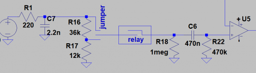
What I can do is to bring it back to 10k and fully disconnect it when I don't need it. Cheap enough with jumpers but it would need a 4pdt switch instead of a dpst if I want to make it easily switchable (for stereo).
That would bring me back to the attached circuit.
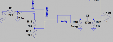
edit: or this variant, inspired of the ovation symphony preamp, which saves one jumper.
What I can do is to bring it back to 10k and fully disconnect it when I don't need it. Cheap enough with jumpers but it would need a 4pdt switch instead of a dpst if I want to make it easily switchable (for stereo).
That would bring me back to the attached circuit.
edit: or this variant, inspired of the ovation symphony preamp, which saves one jumper.
Attachments

Last edited:
No, that breaks the rule of "don't attenuate then amplify" (reduces SNR unnecessarily).Well, I need one divider at the input to accommodate DAC, CD or pro gear on one side and phones, soundcards or legacy gear on the other side.
The other rule is "don't amplify then attenuate" (reduces headroom). This latter can sometimes be violated when you know there's more headroom than is ever needed.
Whenever you see a series resistor on the input to an amplifier you should immediate say to yourself "ah, extra noise, can I reduce/eliminate that resistor?"
And in general its a good plan to boost the input signal to an internal level that's at least as great as the input and at least as great as the output, keeping an eye on the headroom. For a preamp its usually easy to arrange that the power amp clips before the preamp overloads, since power amps usually clip at a few volts input and preamps use +/-15V rails.
Oh and make that volume pot 10k, not 100k. Lower noise, more available, thicker carbon track...
BTW that 7k5 resistor on the input dominates the noise, 4 times the noise power of your input stage opamp.
Last edited:
You are depending on the bass pot for bias to U6, which may result in a huge pulse if the slider temporarily looses contact. I would add a pair of high value resistors (||C1 and to U3) in parallel with the tone controls so the the drop-out is flat audio.
I don't agree. Yes, the resistor adds noise but the source is not zero impedance, and a resistor is the best ESD protection you can do. If this was a phono or mic input then the noise would be an issue, but not at line level.
Whenever you see a series resistor on the input to an amplifier you should immediate say to yourself "ah, extra noise, can I reduce/eliminate that resistor?"
I don't agree. Yes, the resistor adds noise but the source is not zero impedance, and a resistor is the best ESD protection you can do. If this was a phono or mic input then the noise would be an issue, but not at line level.
Except that every rule has to be balanced vs practicality. I'd rather live with a slightly higher noise floor and not run for the volume control every time I'm switching sources. The only way to achieve that is through attenuators, unless I multiply the input stages of course.No, that breaks the rule of "don't attenuate then amplify" (reduces SNR unnecessarily).
In the last schematics isn't the noise reduced by the divider (7k5 and 2k5) ? Sims give me 1.5µV for a 7k5 resistor over the audio bandwidth vs 790nV for the divider.BTW that 7k5 resistor on the input dominates the noise, 4 times the noise power of your input stage opamp.
Actually, the 100k is driven by the market availability of motorized pots. The only ones in ample/easy supply are the 100k ones from the RK168 serie. So once again, I've got to do with what I'm dealt with.Oh and make that volume pot 10k, not 100k. Lower noise, more available, thicker carbon track...
@steveu: good point on the bias problem, I'll do that.
Input noise would be the least of my worries here - 99% of the time, it's the part to the right of the volume control which is dominating output noise.
In this spirit, I would suggest giving U3 some gain (maybe 6 dB) and modifying U2 to be inverting with about the same negative gain. (Vary as needed e.g. if you find you want some extra overall gain. You could also leave U2 and add another inverting stage after it.) Swap outputs around to maintain absolute phase. This will increase levels in the tone control section but not excessively so, making the thing even quieter than it already is.
That assumes that DC/DC output will be the usual +/-12..15 V. +/- 5 V would be a different story, scratch the above then.
Other suggestions:
2n2 of input capacitance seems a bit heavy-handed. Would stick with <=1n. NP0 or film only.
Include at least one set of balanced inputs (maybe two) with a corresponding line receiver circuit. The 1-opamp version should generally do, I'd go with a gain about about -6 dB (possibly closer to -12 dB for +/-5 V supplies). As usual, wire pin 1 to chassis ground, not to local signal ground.
Use dedicated signal and power ground returns as far as feasible.
What does your 5 V supply look like, is it one of these internal metal case jobs? These generally have a PE connection for the mains / EMI filtering that does not go anywhere else (please verify DC isolation from output ground), I suggest hooking that up. While you don't generally want your signal ground to be connected to PE, it definitely should be available for mains filters.
Most audio sources are very low impedance, they are opamps from the CD player, DAC, phono preamp etc, perhaps with 100 ohms on the output for stable cable driving.I don't agree. Yes, the resistor adds noise but the source is not zero impedance, and a resistor is the best ESD protection you can do. If this was a phono or mic input then the noise would be an issue, but not at line level.
Its easy to keep the SNR nice and low with good design techniques so why not?
If you expect a 24bit DAC to perform better than a 16bit one you'd not be tolerating several LSBs of noise from your preamp input section surely? Or put another way a good preamp is expected to perform at least as well as a good source.
ESD protection is best done with appropriate components like TVS diodes which can absorb huge amounts of energy from a spike, A resistor can limit current, but won't necessarily reduce the voltage enough. Consider the standard human body ESD model of many kV discharged through 2k ohms - you need a voltage limiting device capable of rapidly handling amps of current, or a very large resistor indeed...
Thank you for the additional comments.
@sgrossklass:
- yes, the input filter is a bit heavy handed, especially if the impedance of the source is highish. I'll reduce it.
- I follow the logic on bumping the level through the tone controls. But shouldn't I bump the gain in the input stage then, rather than on U3 ? This will also maximize the level on the pot and avoid amplifying the noise of the volume pot. If I boost the input buffer by 6dB, I get about 1µV of noise less at the output than by boosting U3 by 6dB, at various pot positions.
- 5V supply will be either a small linear supply if inside an amp or a 5V/2A usb charger if stand alone.
You have 6-12 dB of gain up front as-is, which is about as much as one would typically be able to afford in this position already. With a 9 dB boost, your 100k pot effectively becomes equivalent to a 12k5 sans boost already, well in the green IMHO. Granted, you have your input attenuator for loud sources. What's the maximum full-scale input level you want before activating that, maybe 1 Vrms or a bit more? Do the math. I don't think you'll end up with a whole lot more than 16 dB. Not a great deal to be gained there.- I follow the logic on bumping the level through the tone controls. But shouldn't I bump the gain in the input stage then, rather than on U3 ? This will also maximize the level on the pot and avoid amplifying the noise of the volume pot.
Of course having all your gain up front is going to give the lowest noise, that's what Mr. Friis says. (For those interested, here's the math.) All the more so if you turn down the volume and essentially eliminate that gain at normal volumes. It's always a tradeoff of noise vs. level handling (distortion / clipping).
Speaking of pots, there are some symbols you can download for them. I think I got mine in the LTspice group. Yeah, I'm often too lazy to use them for a quick sim, too...
Compared to what? 2 µV? 4 µV? 10 µV?If I boost the input buffer by 6dB, I get about 1µV of noise less at the output than by boosting U3 by 6dB, at various pot positions.
A good conventional preamp with no special trickery (e.g. 2-stage volume control) tends to come in at around 4 µV for 16 dB of gain, so that's a good value to shoot for. I suspect you're probably closer to 2 µV. It is not entirely uncommon to find power amps with input noise of this magnitude.
The question is how big is the noise penalty of your tone control, and how much do you gain by running it hotter and attenuating afterwards. Not much of a point if you're increasing internal levels by 6 dB yet noise @ min volume improves by no more than 1-2 dB.
I don't like these 2-prong wall-wart type supplies much. Without a PE connection, they are generally dumping the mains filter leakage currents onto secondary-side ground (causing it to float near half the mains voltage), from where they have a tendency to make their way to earth via audio connections. I don't particularly like it when audio components have audio ground floating near half the mains voltage with an effective coupling capacitance in the nFs.- 5V supply will be either a small linear supply if inside an amp or a 5V/2A usb charger if stand alone.
Last edited:
Ok, rethinking things.
Indeed some smartphones go up to 1vrms output so let's take this as a max baseline for the "low" input, without attenuator. As the opa1641 is on +/-15V and can swing up to the rails, I could bring that up by 18db (8x) and still have some margin for the balance control. But let's be more reasonable and stick with 16db of gain (6x). As my output should also be 1vrms (a common input sensitivity for amps is 1vrms), I've thus 16db to play with.
If I attenuate by 5db in the output buffer, I'm left with 11db to burn with the pot. I need to get rid of these in any case to make headroom for the tone controls. That's the problem of having the tone controls after the volume control... easy to overload. Some kind of clipping alert might be good here. Those 11db are also my reserve of gain for lower sources.
So, with a 1vrms source and at 1vrms output, I'm at 3µv of noise according to ltspice. With a 2vrms source, a 6db attenuator and 1vrms output, 3.3µv. 0.5vrms source, 1vrms output, 3.5µv.
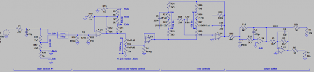
Allright, I adjusted the whole thing.
I keep attenuators at the input. Once everything considered, their noise contribution really isn't much. They can be fully bypassed and provide either -6 or -12db of attenuation.
The input stage is set at +16db. It should not clip unless a source outputting more than 1vrms is directly connected to it.
A 15A log pot such as the rk168 will provide 10db of attenuation when at 2/3 of its rotation. My design goal is to have the preamp at overall unity gain at this setting. So the output buffer after the tone controls is set at -6db.
So the tone control section can at most see an input of 2vrms, which means it cannot clip. It can easily overload the following amp though, but the alternative would be to keep the max "flat" signal 10db under 1vrms... Not great either.
Attachments
- Status
- Not open for further replies.
- Home
- Source & Line
- Analog Line Level
- Opamp based preamp, getting it right