Hi,
I have a Cavalli LC which recently stopped playing music. There is a pulsating sound coming out of the headphones which sounds like a slow motion helicopter in the distance.
There are two push buttons on the front of the amp. One for choosing balanced or SE input, and one for 1x or 3x gain. When I push any of those, the frequency of the pulse is doubling.
You think I have any chance of fixing this with only a soldering station and a multimeter?
If so, where would you start searching for fault?
Best
Theo
Attachments
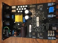

Sounds like the SMPS is not coming up.
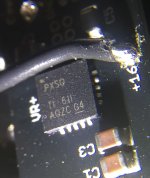
The two bodge wires on the underside should carry +/-16 V, please have a look at them (DC and AC V). I'd guess they are pulsating in sync with the helicopter noises.
There are two potential reasons for why this may happen:
1. Short-circuit protection kicking in due to a short on the output.
2. Weak power supply, often bad caps.
I suggest you power off and measure resistance between both the marked +15V and -15V test points and chassis ground (e.g. the ground screw with the PE cable on it). Repeat with +/-16 V just in case. I imagine you should see a minimum of several hundred ohms everywhere, something <20 ohms would be very fishy. If you do find something, poke at potential candidates and look for the lowest reading, helping to pinpoint the location of the fault.
If there is no obvious short, the power supply itself is suspect. I must say that some of the solder joints on the SMPS transformer look dodgy, as if they had come off the board (one also looks cracked - the 3rd in the row next to R2, on the big trace). That would be consistent with changes when pushing buttons, which applies some force to the board. I suggest you get a loupe / phone camera or similar and inspect these. I hope you've got a decent tip and some flux. I'd tackle the cracked one first and see where this gets you.
A word of warning, be careful around the primary side of the power supply. That big cap has 380 V on it and can still "bite" a good while after power has been turned off. Ideally short it out with an isdolated screwdriver or something just in case (a resistor of maybe 1 kOhm is recommended for bigger ones).
The funny thing is, I was disconnecting an old unused 100 MBit switch just earlier today which was was only blinking dimly any more. Never noticed that it was even still on before. Dead PSU cap(s), most likely, what do you expect from a cheap old D-Link after what probably was 15+ years nonstop.
Last edited:
Hi sgrossklass,
I'm very grateful that you take time to help me out:-D
Ok let's see.
I test these voltages:
+16V - GND = 15.84 VDC and 0.06 VAC
- 16V - GND = 14.08 VDC and 0.06 VAC
+15V - GND= 1.05 VDC and 0.03 VAC
- 15V - GND= 14.02 VDC and 0.05 VAC
Resistance with power off:
+15V - GND = 132K
- 15V - GND = 129K
+16V - GND = rising slowly to around 32K
- 16V - GND = rising slowly to around 37K
Seems like the power switch does not cut mains supply, cause I had to pull the plug to drain the HV cap.
So what do you think?
The +15V seems strange to me with 1 VDC.
The solder joints looks fine.
Theo
Last edited:
Alex retired. Warranty no longer valid. Avenson Audio has agreed to continue servicing CA amps.
Cavalli Audio | Headphone Reviews and Discussion - Head-Fi.org
About – Avenson Audio
Cavalli Audio | Headphone Reviews and Discussion - Head-Fi.org
About – Avenson Audio
Alex retired. Warranty no longer valid. Avenson Audio has agreed to continue servicing CA amps.
Cavalli Audio | Headphone Reviews and Discussion - Head-Fi.org
About – Avenson Audio
Thank´s a lot for the information. As I live in Norway, the cost of shipping and repair is more than a similar second hand unit. So I have to do it myself or get a local repairman to fix it.
sure seems like something on the add on board, probably the 1 regulator chip
you are going to need surface mount repair tools for this one.
you are going to need surface mount repair tools for this one.
sure seems like something on the add on board, probably the 1 regulator chip
you are going to need surface mount repair tools for this one.
Yes. I don´t understand much of this, but should it be 16VDC in on small reg board, and 15VDC out?
When I measure 14VDC on -16V, could that be caused by a faulty chip on the reg board? Or is it something in the psu that causes the low voltage?
so I have pictures of the version one of this board, and the extra board was not there.
for version 2 this add on board is a change. why I do not know, could be some kind of noise issue, or some kind of protection to protect from unbalanced and balanced headphones used at the same time.
likely both of those chips are low dropout regulators set for +15 and -15v
if you have a bench supply you can solder to the +15,-15 and a ground and see if the rest of the amp is working. or if there is a high current short at operating voltage.
you can unsolder the +16 and -16 wires from the adapter board and check again the voltages on those wires. If either voltage is missing, then likely one of the power diodes
just mailing the package twice will cost more than buying the latest version from massdrop.
Last edited:
so I have pictures of the version one of this board, and the extra board was not there.
for version 2 this add on board is a change. why I do not know, could be some kind of noise issue, or some kind of protection to protect from unbalanced and balanced headphones used at the same time.
likely both of those chips are low dropout regulators set for +15 and -15v
if you have a bench supply you can solder to the +15,-15 and a ground and see if the rest of the amp is working. or if there is a high current short at operating voltage.
you can unsolder the +16 and -16 wires from the adapter board and check again the voltages on those wires. If either voltage is missing, then likely one of the power diodes
just mailing the package twice will cost more than buying the latest version from massdrop.
I dont have a bench supply unfortunately.
When I unsolder the wires, the amp won't turn on.
Can I solder +16 wire to -16 and vice versa to see if the low voltage changes side?
Hi sgrossklass,
I'm very grateful that you take time to help me out:-D
Ok let's see.
I test these voltages:
+16V - GND = 15.84 VDC and 0.06 VAC
- 16V - GND = 14.08 VDC and 0.06 VAC
+15V - GND= 1.05 VDC and 0.03 VAC
- 15V - GND= 14.02 VDC and 0.05 VAC
Resistance with power off:
+15V - GND = 132K
- 15V - GND = 129K
+16V - GND = rising slowly to around 32K
- 16V - GND = rising slowly to around 37K
Seems like the power switch does not cut mains supply, cause I had to pull the plug to drain the HV cap.
So what do you think?
The +15V seems strange to me with 1 VDC.
The solder joints looks fine.
Theo
Have to correct the readings a bit. Both + and - 15 reads minus.
+15V - GND= -1.05 VDC and 0.03 VAC
- 15V - GND= -14.02 VDC and 0.05 VAC
Last edited:
I dont have a bench supply unfortunately.
When I unsolder the wires, the amp won't turn on.
Can I solder +16 wire to -16 and vice versa to see if the low voltage changes side?
OK, I mixed up the buttons a little bit. I can tun it on, and the reading is:
+ 16 wire = +15.8 VDC
- 16 wire = - 18VDC VDC
Can I solder +16 wire to -16 and vice versa to see if the low voltage changes side?
NO. does not work that way. In fact that would do a lot of damage.
You could jumper across the regulators, i.e. -16 tied to -15 and +16 tied to +15
that would tell you if the LDO's are in trouble or not.
NO. does not work that way. In fact that would do a lot of damage.
You could jumper across the regulators, i.e. -16 tied to -15 and +16 tied to +15
that would tell you if the LDO's are in trouble or not.
When I bypass the reg board, the amps works amp plays on both channels.
Voltage on - and + is almost equal around 16VDC.
So I suppose the conclusion is that the reg is faulty.
I think it´s to complicated for me to fix, so either I:
1. Get a new board from Avenson Audio
2. Get another board that fits.
3. Run the amp w/o reg board.
Will it be ok to run the amp on 16V for now, or should I drop it to 15V with a resistor?
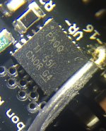
what are the numbers on the 2 LDO chips?
option 1 is highly unlikely or way over priced.
option 3 is the easiest.
absolutely make sure you do not plug in or unplug headphones with the amp on even with the volume at zero.
never ever plug in both unbalanced and balanced headphones at the same time
option 4
make your own perf board with a pair of ldo regulators on it. You should be able to make something by hand using to220 parts that would fit in the case.
what are the numbers on the 2 LDO chips?
option 1 is highly unlikely or way over priced.
option 3 is the easiest.
absolutely make sure you do not plug in or unplug headphones with the amp on even with the volume at zero.
never ever plug in both unbalanced and balanced headphones at the same time
option 4
make your own perf board with a pair of ldo regulators on it. You should be able to make something by hand using to220 parts that would fit in the case.
I have taken some pics of the chips. Maybe you can find them. I don’t know what to search for.
I will wait for the response from Avenson.
If they don’t have it, making one or finding a ready made would be the options.
I like the idea of making one myself. That makes for a nice little challenge for me
Attachments
Last edited:
one is this
http://www.ti.com/lit/ds/symlink/tps7a33.pdf
the other is this
http://www.ti.com/lit/ds/symlink/tps7a47.pdf
http://www.ti.com/lit/ds/symlink/tps7a33.pdf
the other is this
http://www.ti.com/lit/ds/symlink/tps7a47.pdf
one is this
http://www.ti.com/lit/ds/symlink/tps7a33.pdf
the other is this
http://www.ti.com/lit/ds/symlink/tps7a47.pdf
Thanx
+15V/-15V 1A AC / DC Regulator Power Dual Supply input 15-18V UN-Assembled Kit | eBay
I could maybe use half of this
Or a couple of these:
Voltage Regulator
I could maybe use half of this
Or a couple of these:
Voltage Regulator
Last edited:
not the first one. as it clearly will not fit in the box, plus no current limit.
a pair of plus and minus regulators from the second link would definitely work.
a pair of plus and minus regulators from the second link would definitely work.
not the first one. as it clearly will not fit in the box, plus no current limit.
a pair of plus and minus regulators from the second link would definitely work.
Than I will wait for response from Avenson, and if they don't have the original in stock, I will get a pair of the LDOVR regs.
And thank you so much for using your time to help me out. I am very grateful🙂
- Home
- Amplifiers
- Headphone Systems
- Help troubleshooting Cavalli Liquid Carbon