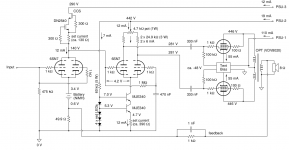
I am thinking about converting my tube amp to use balanced / differential audio input. The schematic of the amp is attached.
I could simply insert a transformer at the input, but maybe it is also possible to do it with a simple modification of the circuit around the tube at the input stage. Any ideas or suggestions? I don't want to change the amp too much (no additional or different tubes please).
Is there a simple circuit modification that would convert the amp from SE to balanced input?
Attachments
Is there a simple circuit modification that would convert the amp from SE to balanced input?
The quick answer is no. You must install a differential input stage and that is not an easy task using the schematic as shown. If you use a transformer, the only advantage is the ability to run long input cables from your differential pre amp output. As we do with balanced line microphones on PA gear and Sound Reinforcement on stage.
...the only advantage is the ability to run long input cables from your differential pre amp output.
I am not so much worried about cable length. I just thought it would be nice to benefit from the cancellation of common noise and distortion in the (+) and (-) lines. In addition, I just don't like asymmetry of the wires and their tasks in SE connection (a "signal" wire and a "zero" shield for to provide a reference for the "signal" and to connect GNDs between signal source and amp input). I am not saying that SE connections are technically flawed, but they don't have the beauty of balanced connections.
Would an input transformer suit your needs? It would be fairly expensive, but it would give you some common mode rejection and you could get rid of the grid leak resistor and you can use the batteries directly on the grid of the tube without the need of an input capacitor.
I am not so much worried about cable length. I just thought it would be nice to benefit from the cancellation of common noise and distortion in the (+) and (-) lines. In addition, I just don't like asymmetry of the wires and their tasks in SE connection (a "signal" wire and a "zero" shield for to provide a reference for the "signal" and to connect GNDs between signal source and amp input). I am not saying that SE connections are technically flawed, but they don't have the beauty of balanced connections.
If you want to take a different aproach for connection why not build your own interconnects? Two wire microphone cable has an almost 100% covering shield, Lemo produces the most exquisite 3-pin connectors.
If you want to take a different aproach for connection why not build your own interconnects?
Been there, done that. Two identical wires with a shield around it, connected to the "GND" wire at one end. But that's not the point here. An SE interface does not magically convert to balanced by simple using a different cable.
The point with the SE connections is that the "shield/cold/black/whaterveryouwantocallit" wire is used for more than just the signal. It's also shield. And it's also a GND connection, which is terminated by essentially 0 Ohm. In contrast, the "center/hot/red/wha..." wire just does one thing: it carries the signal, and it is terminated by a high impedance at the receiver side. This asymmetry is bugging me, and that's why I want to go balanced.
I'll look into transformers and THAT sand parts then. Is there anything particular I need to care about? Recommendations?
UK based Sowter is reasonably close and reputable. Their model 3575 transformer would do what you want.
Notice the need for a low impedance driver. Also, you'd have to change the 475 Kohm grid to ground resistor. Experimentation to obtain the best results is probably in order. My hunch is that something around 12 Kohms will work well. Ringing is definitely to be avoided.
Notice the need for a low impedance driver. Also, you'd have to change the 475 Kohm grid to ground resistor. Experimentation to obtain the best results is probably in order. My hunch is that something around 12 Kohms will work well. Ringing is definitely to be avoided.
Try this; Separate the anodes of the 1st valve. Use a 68k resistor as loading to the second anode and 1k8 to first anode. connect the second anode to the grid of valve 2. Separate the grids of valve 1 and use a 47k resistor from each grid to ground, the grids are then your differential input and the differential result is output on the second anode as output. Your CCS first valve anode load is no longer used and you may need a tweak to the set current on the phase splitter. In my experience that has always been an issue where distortion begins.
Btw, Matthias,
what was the reason to chose a MJE340 as the Cascode CCS's lower transistor? As the CCS impedance is mainly dominated by the lower transistor's hfe, and as this transistor really doesn't see some high Vce, a cheap BC550C might be the better choice.
Best regards!
what was the reason to chose a MJE340 as the Cascode CCS's lower transistor? As the CCS impedance is mainly dominated by the lower transistor's hfe, and as this transistor really doesn't see some high Vce, a cheap BC550C might be the better choice.
Best regards!
Try this;
Separate the anodes of the 1st valve. Use a 68k resistor as loading to the second anode and 1k8 to first anode. connect the second anode to the grid of valve 2.
Separate the grids of valve 1 and use a 47k resistor from each grid to ground, the grids are then your differential input and the differential result is output on the second anode as output.
Hmm, I am not sure I understand how this would work. Wouldn't the 1k8 resistor give a rather high bias voltage + current for the first unit of the input valve, possibly exceeding the limits of the 6SN7? Also, how would the first unit of the input valve contribute to the output of the input stage? How would the anode of the first unit of the input valve be connected to valve 2 (=phase splitter)?
Btw, Matthias,
what was the reason to chose a MJE340 as the Cascode CCS's lower transistor? As the CCS impedance is mainly dominated by the lower transistor's hfe, and as this transistor really doesn't see some high Vce, a cheap BC550C might be the better choice.
Good point. I just used what I had at hand, and didn't touch it anymore once it worked ok (that's why the amp is called the Mac Gyver amp). If I can find some BC550C in my junk boxes I'll put them in next time I open the amps 🙂
You certainly have all the valve sockets in place to convert to an all push-pull amplifier, complete with true differential input.
But alternatively, major gains in cable noise immunity can come from just floating input signal "ground" about 10 Ohms away from chassis "ground". Interconnecting cables feeding the amplifier then use two inner conductors for signal, and the shield for a shield (which is connected at one end only, usually).
All good fortune,
Chris
Last edited:
- Status
- Not open for further replies.
- Home
- Amplifiers
- Tubes / Valves
- Convert tube amp with SE input to balanced