Hi,
Wasn't sure if this type of circuit belongs in power supplies.
Please move it if needed.
I would like to build a basic delay circuit to avoid turn-on thump on power amps. There's a circuit on the web that's on a few different electronics web pages that looks easy enough. Minimal parts. I have a couple of questions.
Does the BC547 need to be a certain grade for this circuit?
For example, grade BC547A,B or C? Coil current is (required current?) 16.7mA.
Also does the 1N4007 convert the 24VAC to 24VDC? The relay I chose is 24VDC. If using straight 24VDC, would it need the 1N4007 rectifier diode?
Relay Specs:
Mfr. Part #: RT424024
Product Category: General Purpose Relays
Manufacturer: TE Connectivity
RoHS: RoHS Compliant
Product: Cube Relays
Coil Voltage: 24 VDC
Relay Contact Form: 2 Form C (DPDT-NO, NC)
Contact Current Rating: 8 A
Contact Termination: Solder Pin
Mounting Style: Through Hole
Switching Voltage: 250 VAC
Coil Termination: Solder Pin
Coil Type: Non-Latching
Coil Resistance: 1.44 kOhms
Coil Current: 16.7 mA
Contact Material: Silver Nickel (AgNi)
Series: RT2
Length: 29 mm
Width: 12.7 mm
Height: 15.7 mm
Packaging: Bulk
Contact Form: DPDT (2 Form C)
Maximum Switching Current: 15 A
Power Consumption: 400 mW
Brand: TE Connectivity / Schrack
Product Type: General Purpose Relays
Factory Pack Qty: 20
Subcategory: Relays
Part # Aliases: 6-1393243-8
Unit Weight: 0.458562 oz
RT424024
Attachments
Does the BC547 need to be a certain grade for this circuit? If using straight 24VDC,
would it need the 1N4007 rectifier diode?
The C grade has the highest beta, so use that one. If using 24VDC input, no diode is necessary.
Use a low leakage type for C2.
Last edited:
A circuit like that is designed for AC.
The 4007 diode naturally only conducts on half the AC cycle, adding some delay in charging the capacitors.
Using DC with it would shorten delay time, requiring an increase in C2/R1 to compensate.
A good delay time would be about 5 seconds before the relay kicks in.
The 4007 diode naturally only conducts on half the AC cycle, adding some delay in charging the capacitors.
Using DC with it would shorten delay time, requiring an increase in C2/R1 to compensate.
A good delay time would be about 5 seconds before the relay kicks in.
Assuming 24vdc, are 35v caps enough? Is there any surge involved?
A 35V rating is fine, the diode takes care of any spikes.
Last edited:
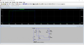
I personally don't like to drive relay coils using an emitter follower; I much prefer to drive them with a common-emitter switch. Or, as illustrated below (taken from the schematic of the Starving Student II page in the diyAudio Store), a common-source switch. The input at top left is a DC voltage, either derived from the PSU or from its very own half-wave rectifier as shown in post #1. Whichever is easiest.
The 2N7000 is an inexpensive small signal MOSFET in the TO-92 package. Hobbyist sites like Tayda and Futurlec sell it very cheaply. And of course Mouser and DigiKey sell it too.
_
The 2N7000 is an inexpensive small signal MOSFET in the TO-92 package. Hobbyist sites like Tayda and Futurlec sell it very cheaply. And of course Mouser and DigiKey sell it too.
_
Attachments

Thanks Mark. Nice and simple.
Unfortunately I already committed my order at Mouser.
We'll see how the schematic in post 1 goes, but it's nice to have options.
Also, been wondering how much current goes through the output stage of most Class A amps and through the relay contacts. I played it safe with an 8 amp contact rating.
Thanks again.
Vince
That looks like a take on a circuit I put together on the forum. Not that I have any exclusive rights to it 🙂
Relay cut-off / mute
Some more here:
where to place mute circuit?
Relay cut-off / mute
Some more here:
where to place mute circuit?
Attachments
That looks like a take on a circuit I put together
I found the same circuit on at least 3 different web sites, none of them on DIYAudio.
I figured it was safe to use for DIY.
They are all classic text book implementations of putting circuit theory into practice, anyone looking to create as simple as possible design would come up with similar designs 🙂
Ideally you want a design that doesn't ramp the relay current up to slowly, one that allows use of small rather than large timing caps and one that allows the circuit to operate normally again (give the full delay) after only a brief on/off cycle.
This design was unique:
Simple Universal Speaker Delay Using A Triac
The 4007 diode naturally only conducts on half the AC cycle, adding some delay in charging the capacitors....
The half-wave doesn't add much delay. It comes to "full" on the first half-cycle going its way. Dozen milliSeconds?
Assuming 24vdc, are 35v caps enough?...
24V rectified to a cap tends to make 33.9V. Minus ripple, minus a part-volt for diode drop, but +plus+ transformer regulation (it may be 28VAC at this very light load).
Just assuming 24.0VAC, I get first cap voltage near 33V. Yes, I have put 35V on 35V caps and they lasted a long time; this is a poor bet. And transformer un-sag puts you nearer 39V. And we like to have 20%-50% de-rating on any cap which will be full-volted "ALL" the time, as this one may. The 35V part will last a while; get a 50V next time you order goodies.
Attachments

PRR - Amigo -
You listed several reliability concerns but left out the scariest of all:
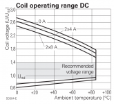
With transformer "un-sag" the circuit applies 37-38 volts across the relay coil. UNFORTUNATELY this is a relay coil rated for 24V DC. Ouch. That takes you well outside the shaded blue "Recommended Operating Range" from the TE Connectivity / Schrack datasheet.
Being good German engineers, the datasheet writers at Schrack denote voltage with "U" and decimal numbers with a comma. Their datasheet figure tells you: if you want to stay out of trouble, especially at high temperature, design your circuits to keep the relay coil voltage between (0.95 * 24V) and (1.4 * 24V). Therefore 37-38 volts is right out.
_
You listed several reliability concerns but left out the scariest of all:
With transformer "un-sag" the circuit applies 37-38 volts across the relay coil. UNFORTUNATELY this is a relay coil rated for 24V DC. Ouch. That takes you well outside the shaded blue "Recommended Operating Range" from the TE Connectivity / Schrack datasheet.
Being good German engineers, the datasheet writers at Schrack denote voltage with "U" and decimal numbers with a comma. Their datasheet figure tells you: if you want to stay out of trouble, especially at high temperature, design your circuits to keep the relay coil voltage between (0.95 * 24V) and (1.4 * 24V). Therefore 37-38 volts is right out.
_
Attachments
I'm using 24v SMPS for a specific project. Do SMPS ramp up over 24v when switched on?
I never looked.
Also, I've never used relays in projects before. Does the 24v rating mean it's the max rating it can withstand or is 24v the rating at which the relay must operate?
Will a 24v relay function with less than 24v?
Thanks for the lesson. 🙂
I never looked.
Also, I've never used relays in projects before. Does the 24v rating mean it's the max rating it can withstand or is 24v the rating at which the relay must operate?
Will a 24v relay function with less than 24v?
Thanks for the lesson. 🙂
I'm using 24v SMPS for a specific project. Do SMPS ramp up over 24v when switched on?
I never looked.
Also, I've never used relays in projects before. Does the 24v rating mean it's the max rating it can withstand or is 24v the rating at which the relay must operate?
Will a 24v relay function with less than 24v?
Thanks for the lesson. 🙂
Relays are rated for voltages within a few volts marked on them - using them with over-voltage circuits could eventually burn out the coil.
As for less, or under-voltages, all relays will trip with roughly half the rated voltage, however this can sacrifice contact reliability.
Rule of thumb - best to stick to within 10 percent of rated voltage.
AKA 24V - 2.4v either side of rating.
I like the use of zener as in post #8
In an older circuit of mine, I was able to get more of a snap action to the relay and indicator LED as well.
If you are slightly more creative, you can integrate a similar circuit into a protection scheme that kills mains on amplifier fault.
In an older circuit of mine, I was able to get more of a snap action to the relay and indicator LED as well.
If you are slightly more creative, you can integrate a similar circuit into a protection scheme that kills mains on amplifier fault.
- Status
- Not open for further replies.
- Home
- Amplifiers
- Power Supplies
- Amp Output Delay Circuit