I have a "Dayton Audio RSS390HO-4 15" Reference HO Subwoofer" which is currently installed in a large (12 cubic foot) vented enclosure and I would really like to see what it can do in a tapped horn. I know how to use hornresponse, but my home computer is DOA at the moment (I'm typing this from work), so I can't really sim it myself. I am, therefore, left at the mercy of the generosity of those on this forum to possibly help me out and sim something that can hit 15 hz or so (I love pipe organ music!). I am hoping to build something with one or possbly 2 bends, but honestly, if I can get horn dimensions, (Mouth area, throat area, lenghth etcetera), I am more than happy to design the actual box on paper myself. I just don't have a usable computer to install and use hornresponse on. Thank you all in advance for any help you can provide😀
Danley DTS concept fold: Danley DTS-10 "Super Spud" DIY kit - AVS Forum | Home Theater Discussions And Reviews
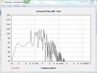
16 Hz pipe fundamental tuning [Fp] attached.
GM
16 Hz pipe fundamental tuning [Fp] attached.
GM
Attachments

Regarding the tapped pipe, If I understand right, I could use something like... miniDSP 2x4 Digital Signal Processor to even out the peaks and valleys, but would otherwise get around 100+ db efficiency in the passband; that might be exactly what I'm looking for! If you can, please remind me because it's been a little while... L12, L34 and L45 are the section lengths in order from the cone to the mouth opening, correct? Or is L12, in the case of a tapped horn, the length of the line between the front of the driver to the mouth opening, or the length of the section "behind" the driver? Sorry... again, it's been a little while since I've used Hornresponse.
Last edited:
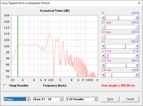
An easy to build 15 Hz capable tapped pipe for your Dayton driver.
With some DSP-EQ you will get a nice in-room response and a fairly wide usable passband.
Regards,
Johannes.
Ok... I believe I have answered my own questions... L12 is the length between the driver center(back side) and the very beginning of the line, L23 is the length from the BACK of the driver to the FRONT of the driver, and L34 is the length from the driver to the terminus/mouth. Correct? I believe I am just about ready to build! I'm not sure when I will be able to aquire the DSP and measurement mic, but I suspect the results will be satisfying even without. Thank you for your help!
I'm not sure when I will be able to aquire the DSP and measurement mic, but I suspect the results will be satisfying even without
I would highly recommend the MiniDSP2X4HD. The large tapped pipe can be a bit overwhelming without taming the peaks. Room acoustics can really wreack havoc with very powerful tapped pipes going this deep into infrasonic territory.
The box should be approximately 183,6 x 54 x 43,6 cm if build out of 18 mm plywood with a double layer (36 mm total) in the baffle to give the driver a good stable mounting and some clearance for the large magnet.
Regards,
Johannes
Attachments
Your numbers are nearly exactly what I came up with once I remembered what the abbreviations in Hornresponse translate into; thanks again! Also, I certainly will, eventually, be investing in the minidsp, though I will probably be utilizing an old Behringer Ultra Q Pro (in the meantime, at least) to tame that sag in the passband. The crossover in the amp should take care of everything above 80hz. I mostly wish I had invested in a measurement mic long ago when I had the money. I have a recording rig with some CAD M179s, but I'm not sure how I would use them, even if my computer were working. Alas...
I have a "Dayton Audio RSS390HO-4 15" Reference HO Subwoofer" which is currently installed in a large (12 cubic foot) vented enclosure and I would really like to see what it can do in a tapped horn.
Now, why would you want to put such a gorgeous-looking driver in a tapped horn? 🙂
I came up with the following sim of a 15 Hz TH that uses a bit of stuffing in the first 25% to reduce resonances, but TBH I wouldn't put this driver in a TH, as usable BW is not likely to extend above 45 Hz (yes, the wonderful-looking graph says that it can go a bit higher, but you've got to take the impact of the x-over on the out of band response into effect, and bear in mind btw that the x-over is not going to have any impact at all on those resonances amplifying any driver distortion that happens within the passband of the TH).
Attachments
I don't think I can build that... it's "the devil"... Just look at that S4 spec. That horn is beelzebub! 😉 On a serious note, I appreciate all of your valuable input, and I certainly love that gorgeous, nearly flat curve on your sim. I think I will try out those numbers with a pad and graph paper and see what I come up with. Honestly, even if it's not perfect, that big cream colored box will be ready and waiting to go back into service. The fun of the build will be worth it regardless of how perfect the final outcome... and I even have a little acousta-stuf ready to go!
Thanks, Brian!
P.S.; I've been reading up on the HornResponse thread all I can say is: Wow! David might need to change the name of the program! "Hornresponse" now seems like a wholly inadequate name for a piece of software that can do that many things!
Thanks, Brian!
P.S.; I've been reading up on the HornResponse thread all I can say is: Wow! David might need to change the name of the program! "Hornresponse" now seems like a wholly inadequate name for a piece of software that can do that many things!
Don't get too hung up on the flat response in the passband - your room is likely going to change that 🙂. I modeled it in 0.5*PI space to sim what the the sensitivity might look like if it was mounted in a corner, but that's a hell of a big box to shove in a corner.
My concerns about the sim are the somewhat narrow usable bandwidth (are your main speakers good to about 45 Hz?) and somewhat small mouth. Given some time I could probably cook up a dual expansion TH with a larger mouth, but the bandwidth is likely to be narrower....
My concerns about the sim are the somewhat narrow usable bandwidth (are your main speakers good to about 45 Hz?) and somewhat small mouth. Given some time I could probably cook up a dual expansion TH with a larger mouth, but the bandwidth is likely to be narrower....
I was hoping it would be modeled in .5pi, because it will definitely be in a corner; I don't have room for it anywhere else! And, of course, I know modeled response and actual, in room response, are going to be different. I just always feel that, unless you have some way to predict in room response (such as in a car where you can somewhat predict the corner frequency and know what to expect in terms of cabin gain), all other things being equal, it's comforting to know that I am a starting with a flatter, predicted, response.
As far as the narrow bandwidth, honestly, I can live with having to use a "mid subwoofer", so to speak, to fill in the "not-so-sub" bass. If it means I get that very high efficiency in the infrasound range, I consider it a worthwhile tradeoff. In the short term, until I can rebuild my home theater, I will be using it with a TV sound bar that has a sub pre-out... I'll pause to let the laughter die down... so, no, my "mains" are not good to 45 hz, but that is not an insurmountable obstacle; I have a compact subwoofer that I will probably daisy chain with this one to fill the gap; less than ideal? Yes, but the weirdness of it appeals to the weirdness in me 😀😉 ! Eventually, when time and budget permit, I will be using it to fill out the bottom end of a pair of line arrays I will be building... more on that WAY later!
As far as the narrow bandwidth, honestly, I can live with having to use a "mid subwoofer", so to speak, to fill in the "not-so-sub" bass. If it means I get that very high efficiency in the infrasound range, I consider it a worthwhile tradeoff. In the short term, until I can rebuild my home theater, I will be using it with a TV sound bar that has a sub pre-out... I'll pause to let the laughter die down... so, no, my "mains" are not good to 45 hz, but that is not an insurmountable obstacle; I have a compact subwoofer that I will probably daisy chain with this one to fill the gap; less than ideal? Yes, but the weirdness of it appeals to the weirdness in me 😀😉 ! Eventually, when time and budget permit, I will be using it to fill out the bottom end of a pair of line arrays I will be building... more on that WAY later!
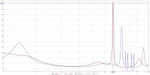
I would prefer some Group Delay at 15 Hz, which is in the infrasonic frequency range and most noticeable as a pressurization of the room, to even more Group Delay at 68 Hz which can be excited by distortion of the driver (second harmonic of 34 Hz an third harmonic of 22.6 Hz) even if crossed over well below the peak in the GD graph.
The TP has a larger usable range and will be easier to cross over to the mains - and even more so considering the large GD peak at 68 Hz for the tapped horn version.
A tapped pipe is much easier to build with only straight non-expanding sections and 90 degree cuts.
Just my five cents.
Regards,
Johannes
Attachments

Last edited:
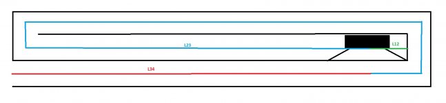
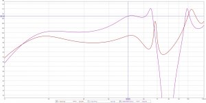
Here is simple stepped dual "expansion" Tapped Pipe design somewhat similar to the ROAR series.
If the last section of the TP is allowed to grow into a large front resonator then the efficiency above 15 Hz increases considerably (+8 dB @ 50 Hz). The upper peak in the GD graph moves down in frequency but is not as extreme as the TH version.
If the last section of the TP is allowed to grow into a large front resonator then the efficiency above 15 Hz increases considerably (+8 dB @ 50 Hz). The upper peak in the GD graph moves down in frequency but is not as extreme as the TH version.
Attachments

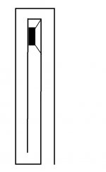
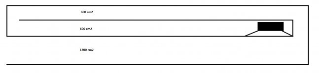
Here is a simple sketch of the frontresonator enhanced tapped pipe.
The slowly rising response of the TP-FR will probably and to some extant compensate for the room gain profile into the infrasonic frequencies, and be easier to integrate with the main speakers.
The slowly rising response of the TP-FR will probably and to some extant compensate for the room gain profile into the infrasonic frequencies, and be easier to integrate with the main speakers.
Attachments
Last edited:
Indeed, Circlomanen, the simplicity of the build definitely attracted me to your design. The truth is, I'm still mulling over what I will eventually build. I'm so excited about the updates to Hornresponse, I really wish my PC was working so I could just use one of these ideas as a jumping off point and go crazy with something! Alas...
I was hoping it would be modeled in .5pi, because it will definitely be in a corner; I don't have room for it anywhere else!
OK, didn't use it since HR's 'infinite' corners don't exist in a typical home, etc., so hard to even guess what a true sub will peak at in response/SPL, but FWIW, here's the larger TH Vs the 15 Hz TP [shadow plot]/0.5pi/800 W, hence a bit more powerful down low.
GM
Attachments
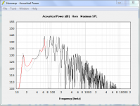
OK, didn't use it since HR's 'infinite' corners don't exist in a typical home...
GM
I must confess ignorance regarding 'infinite' corners; I am guessing they are some sort of theoretical construct, but I can't say that I've ever heard of them or have any idea how they differ from a typical, actual room corner or how said difference will affect what I hear...😕
Real world rooms don't have zero losses due to size, construction, so can't reach the +9 dB/octave of theoretical [cabin] gain like some vehicles, though the better constructed rooms can get close higher up in frequency.
There's been a number of folks in locales where construction must be quite good due to harsh weather and typically get gains in the 1pi loading range down low, but in my 1952 Deep South stick built, floating floor home I only get +3-4 dB depending on the corner, SPL, frequency and then on down to around the corner sub's ~14 Hz max gain at tuning where it just shakes the house. 🙁
A real bummer now that there's so many LFE soundtrack movies and especially some good pipe horn symphony recordings that can at least get as low as what I experienced growing up with a huge pipe organ in a Ga. granite church and one major reason why I became obsessed with large [horn] speaker systems at an early age: Atlanta First United Methodist Church - Wikipedia
GM
Ooooohh, my! I feel your pain. Pipe organs are what fuel my obsession for deep bass, as well. I found this link to the organ at that church on the AGO website...
Atlanta First United Methodist Church - AGO Atlanta
Very nice indeed! The one that grabbed my attention is in Bakersfield, CA...
OHS Database: Instrument Details
The first time I heard a 32 foot pedal note in person, I simply had to find a way to recreate that in my home. There is nothing worse than watching a speaker cone shake without producing a sound.
- Status
- Not open for further replies.
- Home
- Loudspeakers
- Subwoofers
- Tapped Horn