Guys, I am using B&C 6PEV13 6.5" driver mated to a JBL Progressive Transmission horn covering about 250Hz to 2500Hz and driven by a tube amp. There is a .013ft(net) sealed rear enclosure and no throat chamber. The throat is 4.5" diameter. Right now, the FR plots look good but the impedance plot shows a 30+ohm peak at around 480Hz. My question: how important is it to flatten the impedance/resonance? I'm not sure that I can hear any distortion from it but I know resonance adds its own "color" . Additionally, I've read tubes(new to them) need to see a more stable load. Wouldn't flattening this impedance spike benefit both the sound and help the amp? I have this question in another forum so if you've responded there, please don't take this as slight, I just want to get more input. Thanks in advance, Brad
I run a 3 way active system using 0 fdbk SE amps with mid and HF horns and discovered that high source impedance (3 - 4 ohms) and 16 ohm compression drivers were not a great mix. I found in my case that lowering source impedance flattened out the response significantly. (I changed to 8 ohm taps on my amps) You'll need to do response measurements to determine how much of an issue you have if any.
Tube amp topology and their output transformers (and transformerless) varieties vary so much that there is no single answer to your question of the importance of a flat impedance- it would depend on the design, and also how close to the limits of it's output you are driving the amp to whether impedance peaks will have a sonic impact.
This reference can give you some insight:
http://www.vac-amps.com/TechMonographs/VAC Output Impedance Matching-Technical Monograph 90-9.pdf
Since your speaker's frequency response already "looks good", there likely won't be any sonic improvement in efforts to reduce the impedance peak, and the amp won't care for the "help".
I'm not sure it's really an amp issue, but more how the given driver behaves when not driven by an ideal voltage source. I have very limited experience but I can say that JBL 2420/2440/2441 do exhibit measurable variations in frequency response due to amplifier source impedance. Some other drivers may be more or less sensitive to the issue.
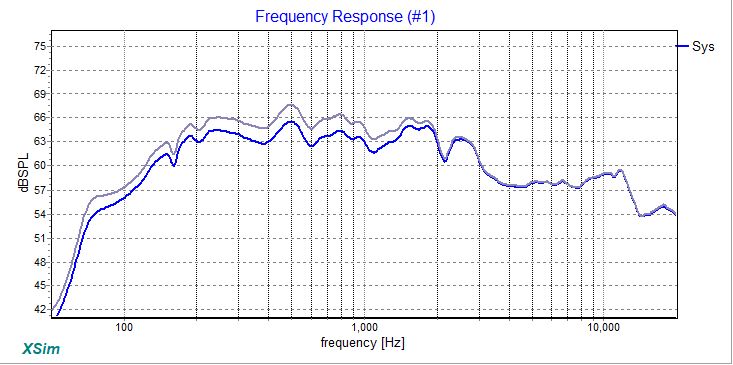
Not the same drivers or horn, but here is a result of impedance compensation (light) and none (dark), assuming an amp having a 2 ohm resistive output impedance.
The impedance of the speaker itself, with(dark) and without compensation:
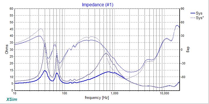
The impedance of the speaker itself, with(dark) and without compensation:
Attachments
Guys, Just taking time to digest all this. I've been crazy busy and have not been able to run charts like bwaslo did...with that said...hmmmmm! So...reducing the resonant impedance(s) by >half dropped output by 2dB with the same FR shape and gave the amp a MUCH better load overall. I understand that this MAY not work in my case but it seems worth a shot. I got onto this idea after completing a set of aperiodic subs. Reducing the resonant impedance DID lower SPL with a better sound while not changing the FR much; but that was with solid state amps. I know tubes have less damping and any resonance is pretty much made more noticeable, hence my desire to see if I could improve my sound, even if a little. Please let me know if I'm missing something. Thanks again, Brad
How about compensation EQ? It certainly worked for my VFET single ended projects (1-2ohm output impedance).
As output impedance rises a portion of the impedance is convolved with the FR (taken will a low output impedance amp) so when output impedance climbes the FR starts looking more and more like the impedance curve.
SE tube amps typically have output impedance of say 1-4 ohms so the impedance starts having a significant impact. When the amp becomes a true current amp (output impedance greater then speaker impedance flat impedance becomes critical.
Some speakers want to see those higher output impedance amps (the Fostex FExx6 series), but here the impedance curve at either end rises and working with the highish output impedance working to increase the LF & HF extension out of the loudspeaker.
Paasive XOs are very often the cause of much impedance variation. Loosing them really helps (ie active of less ways or great care designing the XO.
As an example of what happens with higher output impedance this range of simple BRs using the same driver considers the output impedance of the amp when designin gthe box.
http://wodendesign.com/downloads/King-of-Swingers.pdf
dave
plasnu, yup...shoulda mentioned that I'm using miniDSP for x-over, eq and time correction. So much easier than a room of components.
planet10...it is a Chinese tube amp, Yaqin MC-13s, EL34 based push/pull. I know, not the best and very little literature on the output transformers; all I know is they have a 4ohm and an 8 ohm tap???? Like I said, new to tubes. If I remember correctly, the lowest impedance between 200-2.5KHz was a little over 9ohms with that 36ohm peak around 480-500Hz.
I really owe you guys some screen impedance/fr shots here and I apologize for the delay; the education is MUCH appreciated though!
Output impedance is also defined as damping factor [DF], so do you know what it is?
Anyway, re horns; Altec used impedance compensation on the woofer horns only till DF dropped to negligible values with PP tubes, SS, then turned around decades later and added it to some of its studio monitor HF horns, so go figure.
Some articles to maybe help understand:
DAMPING FACTOR DEBATE
https://web.archive.org/web/2016073...ping-Factor-and-Damn-Nonsense-Floyd-Toole.pdf
https://www.pearl-hifi.com/06_Lit_Archive/02_PEARL_Arch/Vol_05/Sec_23/1385_Critical_LS_Damping.pdf
Damping factor
output-trans-speaker-matching
There's lots more on the net if these aren't sufficient.
GM
As GM says.. But fixing your impedance causes no harm. Put it on a crossover simulator (if you can) and just do it.
Also, not all valve amps have a high Zo.
Also, not all valve amps have a high Zo.
GM...WOW!!! I have looked for good articles on damping and NEVER saw the PEARL article. That truly makes sense and, as the author says, fills in a missing link in my understanding...I think. Correct me if I am wrong but working toward a critically damped speaker system is key to getting the best sound from the SYSTEM...right? Your point from what I understand.
Allen, yea, I think I'll definitely work to flatten it out to be critically damped to tighten up the mids/mid-bass.
Thanks again guys for your patience and direction. I hope to not be a bother.
Brad
Allen, yea, I think I'll definitely work to flatten it out to be critically damped to tighten up the mids/mid-bass.
Thanks again guys for your patience and direction. I hope to not be a bother.
Brad
I'm not certain I was thinking as much as that. Just keeping the response in order is a good start.
I'm not certain whether you are suggesting that the damping factor should be as low as possible. This is not what the article is saying. In case you are..Correct me if I am wrong but working toward a critically damped speaker system is key to getting the best sound from the SYSTEM...right?
If you make your box a little larger you can also lower the system Q. This is obviously not going to be helpful beyond a certain point. If you also then increased the amplifier output impedance to work back toward the original Q, the primary result would be the same as in the beginning.
The typical resistance of a speaker is 6 ohms. In order for an amplifier output impedance to play an insignificant role in the damping, it should be significantly lower.. e.g. 0.6ohms. This is also the output impedance below which it would be considered a Voltage source. Going lower does little.
Allen, I'm re-reading the articles from earlier and I think I jumped to some conclusions. I'll be honest, all this is making my head hurt 😉 but I am enjoying the learning process. I am not an EE but do have a basic electronics background(RF transmissions) that is being tested for certain. I think I'm confusing critically damping the speaker acoustically v/s electrically. So I think I should work to get the speaker impedance as flat as possible in the passband by getting the right enclosure size/horn coupling first. Then I need to figure out the impedance of the amp taps to properly mate the speaker to the correct tap(4ohm or 8ohm) because I want the speaker impedance to be higher than the amp impedance (hopefully by a factor of 10) Am I tracking?
GM...WOW!!! I have looked for good articles on damping and NEVER saw the PEARL article. That truly makes sense and, as the author says, fills in a missing link in my understanding...I think. Correct me if I am wrong but working toward a critically damped speaker system is key to getting the best sound from the SYSTEM...right? Your point from what I understand.
Seems that way, but not really, this article is merely one of the cornerstones of T/S theory, i.e. 'critically' damped = T/S max flat alignment = 0.707 Qtc
Note that 'critically damped' is sometimes erroneously used to describe the technically best possible speaker system alignment: transient perfect 0.5 Qtc.
That said, real world 'best' is the one that works best overall meeting the app's performance goals once the signal chain, room, etc., are accounted for, which usually means it's anything but optimal as a standalone and why OB/IB/sealed or some form of well damped, low tuned vented + various types of EQ is often the 'best overall' in reality.
GM
Last edited:
Also to note when designing speaker cabinets is that the T/S parameters are small signal parameters and that certain specifications, such as Fs, will vary with drive level.
If it helps, you can begin by considering critical damping as Q=0.5 , and assume it is a useable compromise. As pointed out 0.7 is also useable, the difference is not great. The word critical relates to waveform damping, but it is the response that we are more interested in. Some use the term to refer to a critical amount of response shaping. Right or wrong, they are usually considered the same thing.critically damping the speaker
Ok.. The place I usually consider first is the crossover region, given that it is in a vulnerable position and in a band with higher sensitivity to issues. Variations in impedance here are usually the result of acoustic balancing efforts that it would be a shame to upset.So I think I should work to get the speaker impedance as flat as possible in the passband by getting the right enclosure size/horn coupling first.
Brinkman, yea, I'm aware of the small signal value of the T/S parameters. I was reading that you can use REW with the amp and some resistors...have you tried that? If so was it worth the time? Much difference?
Allen, I'm thinking the same thing concerning response primarily. I am using all active(MiniDSP) so no real problems with crossover interaction. I just wanted to quell any resonance in the passband(which is where my resonance is now) in order to get the best transients and uncolored sound. So far I've learned that the damping factor of the amp is not all that important if over 15 max...so getting close to that value by damping that peak will help the electrical matching and also clear up the mids...so a win win...right. Thanks again. I'll try and get this all tested out this weekend but work & family always come first 😉
Allen, I'm thinking the same thing concerning response primarily. I am using all active(MiniDSP) so no real problems with crossover interaction. I just wanted to quell any resonance in the passband(which is where my resonance is now) in order to get the best transients and uncolored sound. So far I've learned that the damping factor of the amp is not all that important if over 15 max...so getting close to that value by damping that peak will help the electrical matching and also clear up the mids...so a win win...right. Thanks again. I'll try and get this all tested out this weekend but work & family always come first 😉
- Status
- Not open for further replies.
- Home
- Loudspeakers
- Multi-Way
- importance of flattening impedance in tube driven horn speaker