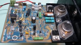
The BLUE capacitor near connector 25/26 looks to have a bulging top on it.
If it is, it must be replaced.
A new one must be installed with the proper polarity.
Replace it on both channels with a 220Uf , 35V lytic.
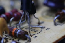
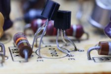
The two transistors at the Q702 location should be touching each other, with a dab of heatsink grease between them, and a zip tie holding them together.
That way, they will track each other better thermally.
Good eye on the Cap. Probably the result of transistor leads incorrect. Made another assumption. EBC
Since the Transistors will be replaced will do as recommended. It will be interesting lead swapping and pairing up. Thanks.
First thing to do with any faulty amp is a good visual inspection.
Look for bad solder joints and damaged components.
If its old then possibly electrolytics on their way out.
Connectors can become oxidised.
Resistors if faulty usually go open circuit or high in value.
I attempted a fix on an old 1980's Maplin amplifier I bought in off ebay.
It worked but was badly distorted.
One voltage didn't look quite right so I checked every component on the pcb for correct value. I did diode check on all transistors. Everything was fine.
I kept coming back to the same transistor where the volts weren't quite right.
So I took it out and diode checked it again. It suddenly hit me that the diode check was the wrong way around. Some bright spark had fitted a pnp instead of an npn transistor !
Just to help the number had rubbed off the transistor with age. I managed to find a replacement only on ebay and the amp was back to sounding great.
Good eye on the Cap. Probably the result of transistor leads incorrect. Made another assumption. EBC
Since the Transistors will be replaced will do as recommended. It will be interesting lead swapping and pairing up. Thanks.
I replaced the Capacitor temporarily with what came from the right channel.
Replaced the Transistors and low and behold the high voltage on left channel has been replaced with .5 mv. The right channel is about 3X higher but not surprising. Will change out Q701 after I give it a listen.
Pictures in the AM. Thanks again.
First thing to do with any faulty amp is a good visual inspection.
Look for bad solder joints and damaged components.
If its old then possibly electrolytics on their way out.
Connectors can become oxidised.
Resistors if faulty usually go open circuit or high in value.
I attempted a fix on an old 1980's Maplin amplifier I bought in off ebay.
It worked but was badly distorted.
One voltage didn't look quite right so I checked every component on the pcb for correct value. I did diode check on all transistors. Everything was fine.
I kept coming back to the same transistor where the volts weren't quite right.
So I took it out and diode checked it again. It suddenly hit me that the diode check was the wrong way around. Some bright spark had fitted a pnp instead of an npn transistor !
Just to help the number had rubbed off the transistor with age. I managed to find a replacement only on ebay and the amp was back to sounding great.
Good find. At least someone else did it to you. I did it to myself.
Playing Herbie Hancock VSOP listening to the new parts. Original crackle is so far not there. It's running and all parts temperature's, seem normal. Will work on right side next.
The power up and power down crackle is still there on left channel only. it's frequency seems to be lower or at least has added bass. (funny but don't know any other way to describe it. So something is still not happy. it may not be on the board. It could be on the chassis in the output circuitry. Very little to be suspect. Some diodes or the Bridge rectifier.
As I bent these leads in place I had to ask my self.. Is this a joke??
Creative if it is...
No paste but will continue work on it. The blown capacitor is temporarily replaced as more parts are on order.
When it plays is sounds great. No consistency on power up & down static.
Sure is nice outside.😉
Creative if it is...
No paste but will continue work on it. The blown capacitor is temporarily replaced as more parts are on order.
When it plays is sounds great. No consistency on power up & down static.
Sure is nice outside.😉
Attachments

Are going to put them face to face with thermal compound on the final install? I see many Carbon Comp resistors, measure the resistance of each and if any are out of tolerance they could be the noise makers.
Craig
Craig
Are going to put them face to face with thermal compound on the final install? I see many Carbon Comp resistors, measure the resistance of each and if any are out of tolerance they could be the noise makers.
Craig
Gonna try on the face to face. Gotta keep leads from shorting. I will say this. These did wonders for my DC offset. Measured well Tp 01 & 02. Adjusts nicely.
On the resistors i will methodically lift leads on one end and measure.
I'm going to put this out there too but it's inconsistent. On Power down the static appears after a time. Slightly after a minute and I think I'm hearing it later as well. A hour or so something is discharging. I'm not next to it. I hear it a room away so i'm not positive it is my Amp. Thanks
Are going to put them face to face with thermal compound on the final install? I see many Carbon Comp resistors, measure the resistance of each and if any are out of tolerance they could be the noise makers.
Craig
If the flat face on each transistor IS facing one another, that's an easy task.
A small drop of heatsink grease on the flat, push them together, and wrap a zip tie to hold them in thermal contact.
IF..... one of them is NOT facing the other, then it's bent down, flat side up horizontal to the board, the other is then bent down on it, flat side down.
This is the "old technician's trick" I've used many times in servicing.
I have no grease so I will make my own. Ready??
I have on hand Zink Oxide and Dielectric grease. 75% 25%
I have no grease so I will make my own. Ready??
I have on hand Zink Oxide and Dielectric grease. 75% 25%
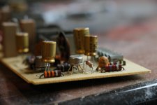
Hello boys & girls. It's only been 8 months since last post but I have not been idle on this. I have real thermo grease and transistors positioned. Since last post I have been mostly using the amp as it seemed to settle down with occasional noise but mostly functioned.
In the mean time I acquired a second H/K 12 Citation that has not been molested. One channel was not working so i replaced the bridge rectofier and one power cap and it was working. I was intending to use the signal board and just swap them to see if the crackle disappeared but alas the second amp went south as well. I have enough parts to recap it as well as I am certain the power caps are toast. Using board #2 in the orig chassis there is no bias voltage in R channel so I am replacing the original differential amp in it to continue the swap test. Here is a pic of the differential amp. Kinda cool.
Attachments
I acquired a second H/K 12 Citation
Hello, please tell me how is the amp sounding.
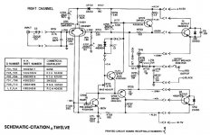
The amp looks very nice and it can produce 120W per channel powerful output.
If it sounds good and I would like to mod it from my Quad 405 PCB.
Quad 405 Mod to Quad 606 series big family
The 405 PCB has two NPN power transistors and the driver transistors can fix on the same heatsink, the op-amp IC can built a DC servo control for it.
Attachments
- Home
- Amplifiers
- Solid State
- Hot Output on H/K Citation 12