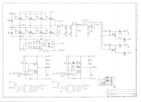
Hello ! Pls help regarding a SL-A1500 driver "paradox" , all IRF 640 are ok, all gate resistors are ok but on power I have + 70 V on speaker output (no protection on red LED , blue LED switched on after initial checkings !) due
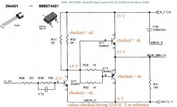
Q11,Q13,Q15 act strange (all checked = ok) on attached diagram I have 15 V on "MOS_DRV_H" , I've suspected Q11 but Q11 is ok.
If Q11 is out, still have 7.5 V on "MOS_DRV_H" (from where ???)
Q11,Q13,Q15 act strange (all checked = ok) on attached diagram I have 15 V on "MOS_DRV_H" , I've suspected Q11 but Q11 is ok.
If Q11 is out, still have 7.5 V on "MOS_DRV_H" (from where ???)
Attachments
I'd suggest that you remove all rectifiers and then check the drive signals if you have a scope.
Pls develop your answer - regarding the reason.
It's a lot of work to remove all rectifiers (at this moment I have available only the upper part of mainboard and most of rectifiers are on bottom part...) and also I don't want to leave unnecessary service traces.
Unfortunatelly I don't have a scope. I haven't use a scope in 40 years of electronics...
")
It's virtually impossible to properly repair class D amps without a scope. A slight problem with the drive waveform will make it unreliable. Using a meter is only guessing.
Even for class B/AB amps, there are a lot of problem that you can't detect without a scope.
Why haven't you used a scope? You don't have to spend a lot of money on one. Any old CRT based scope with a triggered sweep and in good working order will work.
If the amp is like similar amps, it uses TO-220 rectifiers. Apply additional solder, heat all 3 legs at once and it will fall out. Then desolder to remove bridges. It literally takes less than 1 minute to remove and clean up for each rectifier.
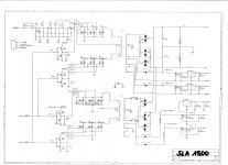
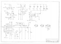
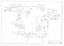
I will borrow an USB- PC based scope. Altough , for my kindly understanding , if after rectifiers I have correct DC voltages , as per diagram , AND incorrect DC voltages on driver output (15 V DC as explained above) , shouldn't I dirrect my attention on a DC problem (like - by example - a defective polarisation on driver's transistors or smooth defective transistor - unlikely to be easy detected) ? I only wonder where from the 15 V DC can appear on one of driver's outputs (the MOS_DRV_L is ok = 0 V, only MOS_DRV_P is defective = 15 V continuously) - on page 4. I will attach the 4 pages of service manual.
Attachments
Last edited:
I need to see the driver signals through the signal path.
Do not ground the USB scope to anything other than the 12v DC power supply ground and then only if necessary. It may be necessary to ground to the source leg of the outputs but ONLY after you discharge the rail caps and remove the rectifiers.
Do you mean MOS_DRV_H?
Do not ground the USB scope to anything other than the 12v DC power supply ground and then only if necessary. It may be necessary to ground to the source leg of the outputs but ONLY after you discharge the rail caps and remove the rectifiers.
Do you mean MOS_DRV_H?
Correction : the MOS_DRV_L is ok = 0 V, only MOS_DRV_H is defective = 15 V continuously.
Pls be more specific , if all rectifiers will be removed and rail capacitors discharged it would become a passive circuit, wich signals exactly to be traced , from where to where ?
Update status:
_all 8 IRF 640 disconnected (all are in good condition)
Problem 01: _unfortunatelly , when powered , no signal passing the drivers - so I have also a problem with preamplifiers / drivers - I will work on it and revert with details concerning input
Problem 02: (the old problem) MOS_DRV_H = 15 V DC continuously - strange because Q11,Q13,Q15 are in good condition - here I am stuck
The amp only uses the TO-220 rectifiers for the main rails. All else will function without them. You leave the outputs in the circuit to load the drive circuit as it would be during normal operation.
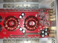
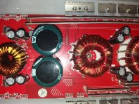
Post a photo of the audio driver board in YOUR amplifier (not one from online).
Post a photo of the audio driver board in YOUR amplifier (not one from online).
also , pls help with U4,U5 ...
U1-TL84C:GENERAL PURPOSE J-FET QUAD OPERATIONAL AMPLIFIERS U2-TL84C:GENERAL PURPOSE J-FET QUAD OPERATIONAL AMPLIFIERS U3-can not find , maybe in shielded box MODU1 U4-integrated circuit is factory (?) polished, no mark on them … can’t find a datasheet … U5-integrated circuit is factory (?) polished, no mark on them … can’t find a datasheet … U6-NE555:Single Precision Timer U7-TL494 : SWITCHMODE PULSE WIDTH MODULATION CONTROL CIRCUIT U8-7805 U9-7805
U1-TL84C:GENERAL PURPOSE J-FET QUAD OPERATIONAL AMPLIFIERS U2-TL84C:GENERAL PURPOSE J-FET QUAD OPERATIONAL AMPLIFIERS U3-can not find , maybe in shielded box MODU1 U4-integrated circuit is factory (?) polished, no mark on them … can’t find a datasheet … U5-integrated circuit is factory (?) polished, no mark on them … can’t find a datasheet … U6-NE555:Single Precision Timer U7-TL494 : SWITCHMODE PULSE WIDTH MODULATION CONTROL CIRCUIT U8-7805 U9-7805
The amp only uses the TO-220 rectifiers for the main rails. All else will function without them. You leave the outputs in the circuit to load the drive circuit as it would be during normal operation.
Post a photo of the audio driver board in YOUR amplifier (not one from online).
No problem on my switching power supply, I have sharp ± 80 V on capacitors. If rectifiers will be removed, nothing to be checked on active amplifier part - where the problem is. Audio driver board is shielded - not as I saw on same internet sinuslive model. See attached photos.
Attachments
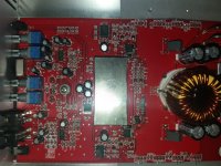
Did you try pulling the cover from the driver board?
Did you confirm that the driver board has all of the required supply voltages?
It may be better for someone else to help you. I have a certain way to go through repairs and if the process I use is not something that you want to do, I can't really help. There are plenty of other users that know these amps.
... also , it's my 1st time servicing a class D amplifier - with driver problems ... and it seems it is not that simple as used to be on classic amplifiers ... this is the reason I bother you so much with questions but in 40 years of electronics I need to understand ahead the service process , I mean - you are a great help and I thank you - only provide a little bit further explanation for step 3 , step 4 after initial steps you've considered ... Thanks again ...
Last edited:
Did you try pulling the cover from the driver board?
Did you confirm that the driver board has all of the required supply voltages?
It may be better for someone else to help you. I have a certain way to go through repairs and if the process I use is not something that you want to do, I can't really help. There are plenty of other users that know these amps.
# try pulling the cover from the driver board - not yet, neither considered at this moment
# driver board has all of the required supply voltages - ± 12 V , confirmed
(...) You are the one started the above servicing process , I think no one would interefere for the moment - pending on results, I appologize for my interferences / questions , my goal was not to bother you but to understand in advance .
Since there is no galvanic separation between driver "MODU1"- Q11,Q13,Q15 preamplifier module - amplifier "outputs" IRF 640, I will check as you said , especially if 15V DC permanent voltage on driver output is triggered or not by faults on MODU1, I will revert with updates
- Status
- This old topic is closed. If you want to reopen this topic, contact a moderator using the "Report Post" button.
- Home
- General Interest
- Car Audio
- SinusLive SL-A1500 driver paradox