Hi Everyone,
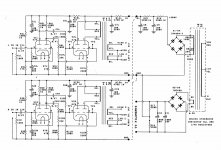
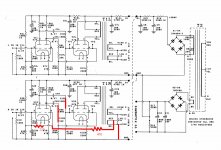
I was wondering if I could get some help with a tube headphone amp that I’ve built for a kit. The circuit diagram is attached and the issue i’m having is a low frequency rolloff at around 120hz. I’ve traced the signal though the circuit and the rolloff occurs at the input of the output transformers. My testing method has been to feed a signal in from my signal generator and to measure points thought the amp with my scope. Everything it spot on up until we hit the output transformer. Could this be caused be a mismatch between the tubes (6j6) and the reflected load? The transformer is a 40k to 33 ohms and the headphones have a nominal impedance of 85 ohms.
Any help would be greatly appreciated. This amp sounds quite good and getting the low end sorted would make it a awesome amp.
Thanks in advance,
Benjet01
Attachments
Any help would be greatly appreciated. This amp sounds quite good and getting the low end sorted would make it a awesome amp.
IMHO, the transformer does not have enough inductance. 40K is ideal but it is suitable for the 6J6 as this has 7-8K plate resistance per triode. Actually it should give you max power. The issue is likely that for REAL 40K at low frequency you need lots of primary inductance which I doubt that tiny transformer has. I don't think you can do much except using a different and bigger transformer with enough inductance. But before I would give it some listening maybe you won't notice much roll off in practice....
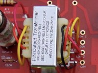
First… the picture you included of the transformer says 40 kΩ → 600 Ω. This would not be 40 kΩ → 33 Ω.
Second… WiseOldTech notes that such a tiny transformer isn't going to give decent low-end “no matter what”. His assessment is actually quite keen. But lets assume for the sake of continuing, that the lil' transformer “has the guts” to get down to 30 Hz or so.
Third… and somewhat more importantly, based on your original post, you say you've injected signal, and all's hunky-dory on the oscilloscope until the primary of the output transformer.
To me this is a “well, maybe everything can be derived from that” trigger.
(Rhetorically) What does an unloaded transformer primary look like at near-DC? Ah, simple enough … like a resistor. A resistor with a resistance of the primary's coil. TaDa. And what does the same primary look like at high frequency? Again, if sufficiently high to be mostly influenced by the inductance of the coil, yet sufficiently low to not be surreptitiously bypassed by the internal capacitance of the thing, it looks like a high-value resistor (in a sense), following the usual inductance-vs-frequency law:
Anyway, you can look it up, or just use a bit of trig to figure out that ZNET as a function of frequency is
So… go measure the DC resistance of the output transformer primary. Post it. We can use that and your below–120 Hz observation to derive the actual inductance of the primary. It undoubtedly is a bit too small to support transformation below some FCUTOFF. You have empirically determined that. The 0.47 µF coupling capacitors both on input, and between first-stage amplification-and-inversion are not the culprits, either. Most likely, a wimpy transformer.
Just saying,
GoatGuy ✓
LOL… because he desired (and was promised) Toobz! GoatGuy ✓
PS… in the ZNET example I gave, you can also quickly figure out “how much” of the primary AC is being 'transformed'.
Hope it helps a bit. GoatGuy ✓
Second… WiseOldTech notes that such a tiny transformer isn't going to give decent low-end “no matter what”. His assessment is actually quite keen. But lets assume for the sake of continuing, that the lil' transformer “has the guts” to get down to 30 Hz or so.
Third… and somewhat more importantly, based on your original post, you say you've injected signal, and all's hunky-dory on the oscilloscope until the primary of the output transformer.
To me this is a “well, maybe everything can be derived from that” trigger.
(Rhetorically) What does an unloaded transformer primary look like at near-DC? Ah, simple enough … like a resistor. A resistor with a resistance of the primary's coil. TaDa. And what does the same primary look like at high frequency? Again, if sufficiently high to be mostly influenced by the inductance of the coil, yet sufficiently low to not be surreptitiously bypassed by the internal capacitance of the thing, it looks like a high-value resistor (in a sense), following the usual inductance-vs-frequency law:
Z = 2πFL
Say, for example that the lil' transformer has a primary inductance of oh, 2 henries. And your sig-gen is putting out 5,000 Hz. the formulaZ = 2πFL
Z = 6.28 × 5,000 × 2
Z = 62,800 Ω
then applies. Quite a bit different from the maybe 500 Ω of DC resistance the primary has at the lowest end. (actually what did you measure as the DC resistance?)Z = 6.28 × 5,000 × 2
Z = 62,800 Ω
Anyway, you can look it up, or just use a bit of trig to figure out that ZNET as a function of frequency is
ZNET = R / sin(atan2( R, Z(f) ))
ZNET = R / sin( atan2( R, 2πFL ))
ZNET = 500 / sin( atan2( 500, 2 × 3.1415 × 100 Hz × 2 Hy ))
ZNET = 1,350 Ω
See what's going on? At a lower frequency (than the first case of 5,000 Hz) the resulting net impedance becomes only 1,350 Ω. To you observing the oscilloscope trace, this is definitely going to look a lot like “the response is falling off somewhere below 120 Hz”. 1,350 Ω vs. 62,800 Ω. ZNET = R / sin( atan2( R, 2πFL ))
ZNET = 500 / sin( atan2( 500, 2 × 3.1415 × 100 Hz × 2 Hy ))
ZNET = 1,350 Ω
So… go measure the DC resistance of the output transformer primary. Post it. We can use that and your below–120 Hz observation to derive the actual inductance of the primary. It undoubtedly is a bit too small to support transformation below some FCUTOFF. You have empirically determined that. The 0.47 µF coupling capacitors both on input, and between first-stage amplification-and-inversion are not the culprits, either. Most likely, a wimpy transformer.
Just saying,
GoatGuy ✓
nigelwright₇₅₅₇;5849826 said:Why not use a MOSFET output buffer to get rid of the transformer ?
LOL… because he desired (and was promised) Toobz! GoatGuy ✓
PS… in the ZNET example I gave, you can also quickly figure out “how much” of the primary AC is being 'transformed'.
VXFRM = Z / (Z + R)
VXFRM = 2πFL / (R ⊕ 2πFL)
where…
R = 500 Ω
F = 100 Hz
L = 2 Hy
then…
VXFRM = 6.28×100×2 / (500 ⊕ 6.28×100×2)
VXFRM = 1257 Ω ÷ 1757 Ω
VXFRM = 0.72 … or 72% of whatever is signal measured across primary
OK! Now you're armed and dangerous. VXFRM = 2πFL / (R ⊕ 2πFL)
where…
R = 500 Ω
F = 100 Hz
L = 2 Hy
then…
VXFRM = 6.28×100×2 / (500 ⊕ 6.28×100×2)
VXFRM = 1257 Ω ÷ 1757 Ω
VXFRM = 0.72 … or 72% of whatever is signal measured across primary
Hope it helps a bit. GoatGuy ✓
If your signals that drive the amp are big (and you only need a voltage gain of 1X or less), 3V peak from a CD player is way too much signal for some 85 Ohm phones). In that case, you can try the following to move the rolloff from about 120Hz down to about 60 Hz (one octave lower):
Revise the circuit: Parallel the 6J6 tubes and drive the transformer in Parallel push pull. Apply the signal to 2 grids of 2 triodes that drive one side of the Output primary. Connect the other 2 grids to ground through a 1k grid stopper. But how to get phase inversion to drive the Parallel push pull? . . . Use a current sink in the cathodes and tie all 4 cathodes together to the current sink. You will have a self-inverting stage. The Parallel plates will drive the output transformer primary with 1/2 of the impedance of the original amp circuit, so the low frequency response will now be 60Hz.
You will have to remove the ground from the 220 Ohm resistors of the filament supply. Then ground the + side of the filament supply. Now you have a minus (-) 6.3V supply to power a LM317 current sink. The LM317 "Output" pin connects to the current sense resistor; the other end of the current sense resistor connects to ground. The LM317 "Control" pin connects to ground. The LM317 "Input" pin connects to all 4 6J6 cathodes.
The LM317 current source (sink) is fairly will documented. If you want to look for the circuit of the ODDWATT amps, look for EL84 and other versions that use LM317 current sinks.
The 6J6 does not need much bias voltage, but the LM317 has a burden voltage of 4.25V, so that is why you need to use the -6.3V filament supply to make it work for 6J6 tubes.
You will get push pull tube sound, with a little bit of 2nd harmonic SE tube sound added to that.
Last edited:
Big thanks to all the responses so far. I’m blown away by the generosity of knowledge. Greatly appreciated!!!!!!!!
I’ve always suspected the output transformers weren’t up to scratch. This whole kit costs $89 AUD so I wasn’t expecting top shelf performance. In actual fact the amp sounds quite good, so good that I purchased another and rebuilt it using better components and a reworked power supply (see attached pic). The results were quite impressive and this issue with the bottom end has been the only thing holding this back from being and exceptionally great sound amp. I’m more than happy to sink a few $$$ into this if a suitable transformer can be found. I won’t need the dual secondary’s as I’ll only be using this with a pair of Focal Utopia headphones (85 ohms nominal impedance see attached pic). Ive also attached a frequency response plot showing the tube amp and also the response from another amp I have.
I’ll do some more measurements and get to you guys. Hopefully together we can sort this out.
Thanks once again,
Benjet01
Yes. That the impedance and phase
I’ve tried the headphones on the 300 ohm winding of the transformer and this produces flabby bass and muffled treble. I have another pair of headphones with have an impedance of 300 ohms, they seem to exhibit the same issues although I haven’t yet plotted a frequency response to quantify this. I’ll warm up the scope today and see what other information I can supply. I’ll work out how to measure the inductance as well.
Sorry about the last two posts, my grasp of the English language is apparently not the best when I’ve just woken up. So answer to your question is yes, that is the impedance of the Utopias.Is Post # 14 a measurement of the Focal Utopia Headphones?
I’ve tried the headphones on the 300 ohm winding of the transformer and this produces flabby bass and muffled treble. I have another pair of headphones with have an impedance of 300 ohms, they seem to exhibit the same issues although I haven’t yet plotted a frequency response to quantify this. I’ll warm up the scope today and see what other information I can supply. I’ll work out how to measure the inductance as well.
Your phones load the 6J6 from 200 Hz and up (phones are 100 Ohms decreasing to 80 Ohms). The output transformer inductance loads the 6J6 from 20Hz to 100Hz. Those frequencies are rolled off because of that. An output transformer with more inductance will actually give a Bass lift from 30 Hz to 100 Hz. That is because your phones are 200 Ohms or more there.
There are voltage dividers between the first and second stages to throw away 8 dB of gain. You can remove these and add 8 dB of negative feedback from the output to the first stage; gain will be the same with a flatter frequency response. Resistor values are a guess... and transformer leads may have to be reversed (it'll oscillate if feedback is positive).
Attachments
Last edited:
If you manage to that please use a resistor load and a osciloscope, you may need another pair of ears and headphones if you plug yourself during tests if that oscillates 😀
Last edited:
Thanks Tom, I’ll give that a go. I have two of the amps so I’ll implement that mod in one and compare them.There are voltage dividers between the first and second stages to throw away 8 dB of gain. You can remove these and add 8 dB of negative feedback from the output to the first stage; gain will be the same with a flatter frequency response. Resistor values are a guess... and transformer leads may have to be reversed (it'll oscillate if feedback is positive).
Hi 6A3sSUMMER, the biggest issue with changing the transformers is finding suitable replacements. Any suggestions would be greatly appreciated.Your phones load the 6J6 from 200 Hz and up (phones are 100 Ohms decreasing to 80 Ohms). The output transformer inductance loads the 6J6 from 20Hz to 100Hz. Those frequencies are rolled off because of that. An output transformer with more inductance will actually give a Bass lift from 30 Hz to 100 Hz. That is because your phones are 200 Ohms or more there.
Adding a200 uf capacitor across the cathode resistor (R 12) of the output tubes may help a little
- Status
- Not open for further replies.
- Home
- Amplifiers
- Tubes / Valves
- Need help with output transformers on a tube amp