Hello guys,
I do soldering for years and I'm still missing some basics. GND is part of it. 😱
I have few strong toroidal transformers, but non has V-GND-V. I have two wires AC primary and two wires AC secondary. How I can make missing ground?
I know that some custom made toroidal has leaded wire from the middle of secondary wiring, I suppose it should be the ground...
Well I would like to make some GND on toroidal transformers, because I will need V+ GND V- for my amps. Any idea? 🙄
Thanks for help!
Milan
I would like to make some GND on toroidal transformers, because
I will need V+ GND V- for my amps.
Most toroids now have two secondaries, instead of one center-tapped secondary.
To get a center tap, just connect the two secondaries in series, with the correct
relative polarities. Each secondary should be rated for the proper voltage needed.
Last edited:
use ground from wall socket direct to chassis.
It is really that simple? I thought it will be more sophisticated when audio amp will be powered. And GND with speakers will be shared. Is that OK? I guess to avoid noise I should use some coils... 😕
Also in emi/rfi filters are Neutral and Live shorted to GND over caps.
It is really that simple?
No, there is a misunderstanding. This has nothing to do with the utility safety ground.
The center tap of the series secondaries is the power supply common (0V),
which may or may not be connected to the utility safety ground.
Attachments
Last edited:
Most toroids now have two secondaries, instead of one center-tapped secondary.
To get a center tap, just connect the two secondaries in series, with the correct
relative polarities. Each secondary should be rated for the proper FWCT voltage needed.
Center Tapped Full Wave Rectifier - File Exchange - MATLAB Central
I was thinking about connecting two secondary wirings! But I was not so sure... It's better to ask somebody who's really experienced. Thank you!
And what I should do with two transformers which has only one secondary wiring? I was reading that secondary wiring is below primary wiring, so I guess I won't be able to do modification.
Last edited:
what I should do with two transformers which has only one secondary wiring?
I was reading that secondary wiring is below primary wiring, so I guess I won't
be able to do modification.
Please do not attempt to modify the transformers, this is dangerous.
If each transformer has the correct secondary voltage, you could
make a single DC supply with each, and then connect the two DC
outputs in series, with the connection point serving as the common (0V).
This is not ideal compared to a single transformer, but it would work.
Take two of those transformers, connect the primaries in parallel and the secondaries in series maybe (or actually you should first give each transformer its own fuse before connecting the mains sides in parallel).
MilanAudio, what you are calling GND is really 0V.
Yes, perhaps. On the scheme is written 35+ GND 35- and the GND is shared with one speaker wire, amps are two mono blocks.
Well, if it would be up to me I would just connect dc and forgot about the ground but it would not be 100% OK.
Please do not attempt to modify the transformers, this is dangerous.
Thank you again. I won't.

What you call "Gnd" is actually secondary *center tap* ... which you do NOT have.Hello guys,
I do soldering for years and I'm still missing some basics. GND is part of it. 😱
I have few strong toroidal transformers, but non has V-GND-V. I have two wires AC primary and two wires AC secondary. How I can make missing ground?
I know that some custom made toroidal has leaded wire from the middle of secondary wiring, I suppose it should be the ground...
Well I would like to make some GND on toroidal transformers, because I will need V+ GND V- for my amps. Any idea? 🙄
Thanks for help!
Milan
It is NOT
which is completely unrelated.use ground from wall socket direct to chassis.
It is NOT
because there are NOT two secondaries.just connect the two secondaries in series, with the correct
relative polarities
If you have two exactly alike transformers then
applies.If each transformer has the correct secondary voltage, you could
make a single DC supply with each, and then connect the two DC
outputs in series, with the connection point serving as the common (0V).
This is not ideal compared to a single transformer, but it would work.
You have told us nothing detailed about your transformers ... you ask and we are supposed to guess? 🙄 but IF they have a single 25VAC secondary each then each can feed a bridge rectifier and a single capacitor (say, 4700uF x 50V) to have a single 35V supply.
Then you can connect two such supplies in series , ground the center point, and end up with a suitable 35+35V DC supply for your amplifier.
What Rayma said on his second post.
Please confirm/deny this supposition, we can´t go on otherwise..
Greetings to Argentina! Thanks! I have toroidal transformer with two secondaries: 2x24V. And another transformer 1x27V and few more.
Now is too late, I'm in bed, it's after 1AM and I should be deeply sleeping. Tomorrow I will make it clear even more with photos and simple schemes.
Now is too late, I'm in bed, it's after 1AM and I should be deeply sleeping. Tomorrow I will make it clear even more with photos and simple schemes.
So here I am again
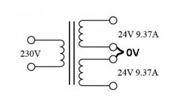
Here is one transformer:
Co I will connect two wires - secondary and after rectifier (it will give 48V together) and after rectifier I will get aprox +37V 0V -37V, correct?
May I divide each wire (+37V, 0V and -37V) into two and power up two amp modules?
Or should I have something like this? 🙄
Here is one transformer:
An externally hosted image should be here but it was not working when we last tested it.
Co I will connect two wires - secondary and after rectifier (it will give 48V together) and after rectifier I will get aprox +37V 0V -37V, correct?
May I divide each wire (+37V, 0V and -37V) into two and power up two amp modules?
Or should I have something like this? 🙄
An externally hosted image should be here but it was not working when we last tested it.
I will connect two wires - secondary and after rectifier (it will give
48V together) and after rectifier I will get aprox +37V 0V -37V, correct?
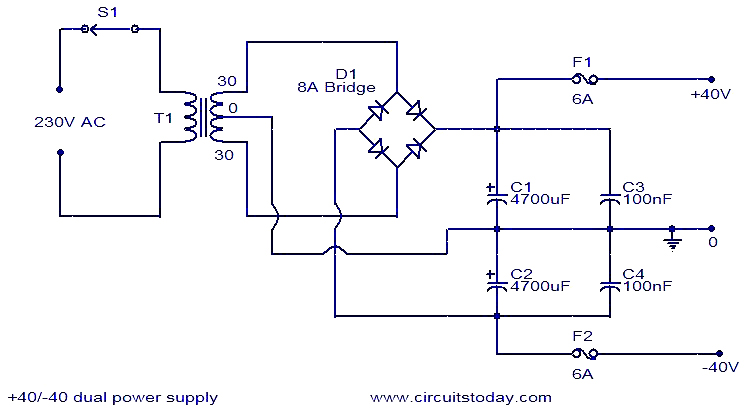
Here is the circuit you want. The two secondaries must be connected
together in the proper relative polarities to work. This may drive either
one or two amplifier channels, and will output +/- 35VDC.
https://www.electronics-notes.com/images/diode-full-wave-bridge-rectifier-dual-supply-01.svg
Last edited:

Here is one transformer:
An externally hosted image should be here but it was not working when we last tested it.
This one is fine.
Conect top of bottom winding to bottom of top winding and that is your center tap.
Then get a nice bridge rectifier, 12A to 35-40 A
Add two capacitors, 4700 x 50 is fine, 10000 x 50 even better and buils a very conventional 35+35V DC supply:
Similar to this one but with your own values of course:
EDIT: same as Rayma posted.
You need to know the phases of the secondaries, see this thread How to determine phase of transformer secondaries?
I f you start making test with transformers connections always use a usual lightbulb in series with the mains ... if your connections are correctly done the lightbulb will not glow and it will make no differencet at all ... but if you make a mistake it will glow and most of all it will limit the current and you will not damage anything.
Light Bulb Current Limiter Build Thread | The Gear Page
Light Bulb Current Limiter Build Thread | The Gear Page
- Home
- Amplifiers
- Power Supplies
- Toroidal transformer, where is the GND?