Antonio, in reply to your question in post 47: consider a simple complementary output stage with just one NPN and one PNP output transistor pair. If they are biased optimally, let's say, or higher, and you are able to drive them with a constant current source, then a change in current could either go into the NPN or share the split with the PNP or go into the PNP. If the gains do not change much with current (an assumption which is not true but truer for modern "linear gain" types) then the total output current change will be constant. Example: suppose you had a design with such output transistors with a gain of 100 each. The VAS might run at 100 mA. Suppose it changed by 10 mA. If the NPN were on, and the PNP off, the output would change by 1A. If they were both on and roughly equally biased, 5 mA might go each way and each transistor would change current by 0.5A, totalling 1A. Any combination also works. The trouble is that you can't have current bias to high frequencies usually, and a low impedance drive requires using gm instead of gain. So gm applies for a low impedance drive. And the main issue is that the crossover region still generates a discontinuity dynamically due to base charges, which means in practice that there is an optimal lowish bias current for Class AB amplifiers, which may become worse in high bias Class AB and only disappear again in Class A. This is because of the stored base charges when handling high frequencies. One cure is to use a low impedance drive, so we're back to gm again...
John
John
Hi,
Consider a 100W amplifier. Consider its perfect up to 10W. Consider clamping
diodes that control 100W clipping behaviour. Consider the "problem" that these
diodes increase, in percentage terms the distortion levels just below clipping.
On paper no diodes is better, but the aural reality can be very different.
IMO high bias AB versus optimum bias AB has similar issues, the reality.
High bias AB moves the issues away from the low power performance.
rgds, sreten.
Last edited:
Hi,
Consider a 100W amplifier. Consider its perfect up to 10W. Consider clamping
diodes that control 100W clipping behaviour. Consider the "problem" that these
diodes increase, in percentage terms the distortion levels just below clipping.
On paper no diodes is better, but the aural reality can be very different.
IMO high bias AB versus optimum bias AB has similar issues, the reality.
High bias AB moves the issues away from the low power performance.
rgds, sreten.
Hi sreten,
When talking about clamping diodes it is important to bear in mind whether they are inside the feedback loop (like Baker clamps typically are) or outside the feedback loop (like soft clipping ahead of the amplifier. Both will control clipping behavior, but the ones inside the FB loop will not usually materially affect distortion measurements. The ones outside the loop, like the soft clipping I described in my book (Klever Klipper) will increase distortion beginning at power levels below clipping, so on paper, as you say, distortion measurements are worse. It has been my experience that the introduction of the soft clipping diodes improves the overall sound, especially if clipping is involved. The distortion they introduce is relatively soft and benign, although it is mostly third instead of second harmonic.
As I've said before, high-bias class AB (what I sometimes call class AAB) is certainly preferable to under-biased class AB, but it does in many cases introduce distortion that can be of moderately high order, so there is a tradeoff with the size of the class A region. Of course, the size of the class A region is in proportion to the total amount of idle bias, and that is in turn often limited by thermal stability considerations. Use of smaller RE values, like 0.1 ohm, permit a higher value of optimal class AB bias, but often invite thermal stability problems, especially if medium-sized gate stopper resistors are used (explained in my book).
Alternatively, you can build a more conservative amplifier with more output pairs in parallel, then use 0.22 RE and have a larger total idle bias with about the same thermal stability (maybe needing a larger heat sink, but heat sink size may be dominated by 1/3 power dissipation considerations anyway).
Cheers,
Bob
(what I sometimes call class AAB)
Good one, would save a lot of idle talk.
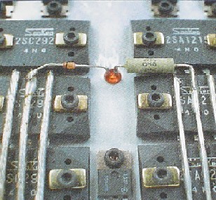
From the old record player : www.audiolabor.de/images/stories/audiolabor/stark-service.pdf
(~$5K/pair in 1982)
Look Ma, Vas/Driver devices snug close to the power outputs => www.diyaudio.com/forums/attachments...8768078-increasing-bias-amps-stark-output.jpg
Last edited:
Antonio, in reply to your question in post 47:
John,
Thanks for your explanation.
I definitely wasn't thinking along the lines of driving the output stage directly from a current source. I need to work on my expanding the envelope when reading some of these posts.
Thanks
-Antonio
Hi sreten,
..... but often invite thermal stability problems, especially if medium
-sized gate stopper resistors are used (explained in my book) ......
Cheers,
Bob
Hi Bob,
Is this the case with a single BJT output pair and say 4.7R gate stoppers ?
(I'm trying to understand the stability of the DXamp, circuit posted earlier,(#25),
this has no Re's, 4.7R g.s.'s and allegedly a Vbe bias thermal tracker is optional,
though I intend to bolt the Vbe mutilplier to back of one device as shown, (#48) )
Does stability vary with the standing current chosen ? seems it might .....
rgds, sreten.
I'm going to go through the what seems excellent LTSpice tutorial in your book ....
Last edited:
Without emitter resistors all parameters (AC and DC) will be poorly defined.
Hi,
Of that I have no doubt, nevertheless the DXamp doesn't have any,
only 4.7R resistors in the bases, the effect of which depends on Beta ?
Even trying to work out what the optimum class B bias is, is difficult ....
Hfe for both devices seems to increase with junction temperature,
the bulk Rb and bulk limit to how low device Re can go is unknown,
(well to me at least), I wonder how good a LTspice sim would be.
For sure leaving out a typical component complicates matters a lot ......
I'm thinking for some devices that can do 100W class B (Self) I'm looking
at about 20W to 25W max AB, and around 5W to 6W in class A region.
Otherwise it will blow up ...... there is no protection of any sort ......
rgds, sreten.
Output devices are 2sc5200 and 2sa1943.
Last edited:
Member
Joined 2009
Paid Member
FWIW my original post is about the inevitable step in the transfer characteristic for high bias AB, and the best approach to ameliorate any detrimental effects.
I had always understood there were four choices:
1) optimal bias (as per D. Self) which this thread is not about - based on a combination of Re and idle current such that the voltage drop across Re is around 26mV on each output device. Lower Re means lower distortion but higher idle current and requires more careful control of output device temperature.
2) class A bias in which you essentially operate in Class A for all normal listening and the amp only moves to class B for peaks and parties. The inevitable step in the transfer characteristic is simply tolerated because by this time you're playing it really loud
3) don't use BJT devices, the preference being lateral MOSFETs which people report as sounding better at high bias regardless of co and benefit at higher bias from having stable temperature dependence
4) use the Broskie approach to fixing the transfer characteristic:CCDA & Class-AC
So far I prefer combination of 1) and 2) with multiple output devices. The project that has inspired my own design (TGM3) of this type was by Roender, a very nice looking amplifier indeed: http://www.diyaudio.com/forums/solid-state/111756-rmi-fc100-single-stage-audio-power-amplifier.html
Also of interest perhaps...
http://www.edn-europe.com/classbamplifierhasautomaticbias+article+3625+Europe.html
http://www.angelfire.com/ab3/mjramp/classb.html
Last edited:
Hi,
I can see the appeal of multiple output devices and low Re to give a significant
standing current with optimum bias for the output stage. I guess the issue
is with the DXamp with no Re's is what is the optimal current first.
rgds, sreten.
I can see the appeal of multiple output devices and low Re to give a significant
standing current with optimum bias for the output stage. I guess the issue
is with the DXamp with no Re's is what is the optimal current first.
rgds, sreten.
Member
Joined 2009
Paid Member
Even in the DX there is Re, just not an explicit resistor. The internal Re of the devices themselves is not negligible and there will be some resistance in the wiring. Using a bias current based on a calculation of these 'parasitic' resistances may yield a starting point to deciding on a bias. I was very surprised to see no Re's on this amp, I think it would be better to include them and make it a 'safer' amp - but DX has built more amps than I've had hot dinners...
p.s. of course, the DX is not remotely in the same class as Roender's amplifier.
p.p.s. I'll be back in Old Blighty this month for a vacation (UK is my birthplace) but unfortunately not that close to Brighton.
p.s. of course, the DX is not remotely in the same class as Roender's amplifier.
p.p.s. I'll be back in Old Blighty this month for a vacation (UK is my birthplace) but unfortunately not that close to Brighton.
Last edited:
The sim shows that the internal parameters of the transistors do the <stabilizing>: pic1 is the original OP stage swept from 0 to 100°C.Is this the case with a single BJT output pair and say 4.7R gate stoppers ?
(I'm trying to understand the stability of the DXamp, circuit posted earlier,(#25),
this has no Re's, 4.7R g.s.'s and allegedly a Vbe bias thermal tracker is optional,
though I intend to bolt the Vbe mutilplier to back of one device as shown, (#48) )
Does stability vary with the standing current chosen ? seems it might .....
Pic2 is the same without base stoppers: little difference.
In both cases, the Iq varies in a 10:1 ratio, even with zero delta T° between the transistors: this means you need a pretty good common heatsink to stay out of troubles.
Pic3 shows an increase in Iq to ~600mA: the relative variation is much smaller.
Attachments
I've been trying to get temperature onto the horiz axis but it doesent want to, sez illegal or unknown parameter when i try entering temperature instead of time.
Hi,
Right. I've just bought a massive FOAD heatsink, I'm taking the saying
there is no such thing as a heatsink that is too big absolutely literally.
Seems it will be a good idea in this case ......
300mm long, 150mm high, 30mm fins + 10mm baseplate, 0.35C/W, 2.5 Kg.
Will be the front panel of a probably open power amplifier with wooden base.
Should do the job ...... for both channels ...... £20 is fairly cheap ......
rgds, sreten.
Large heatsink for amplifier/power supply/led/inverter | eBay UK
Issue now is how far I can push the output devices with the above ......
I suspect not a lot due to the thermal resistances ......
Last edited:
Brute force is only part of the solution: if the Rth of the Junct-to-heatsink is much larger than the heatsink itself, the compensating Vbe multiplier will see much reduced temp variations, and this could lead to thermal runaway.Hi,
Right. I've just bought a massive FOAD heatsink, I'm taking the saying
there is no such thing as a heatsink that is too big absolutely literally.
300mm long, 150mm high, 30mm fins + 10mm baseplate, 0.35C/W, 2.5 Kg.
Should do the job ...... for both channels ...... £20 is fairly cheap ......
rgds, sreten.
The contact between the Vbe mult. and the OP transistors has to be near perfect, and only then can you add the heatsink.
Anyway, if you want to avoid this kind of difficulty, you should consider class AC (mentionned for the third time, not including Bigun's one), or something like the Circlophone, which is also a kind of hi-bias, class AAB approach.
Dispensing completely with emitter resistors, without any good alternative generally ends with molten silicon, sooner or later.
I've been trying to get temperature onto the horiz axis but it doesent want to, sez illegal or unknown parameter when i try entering temperature instead of time.
Attachments
Brute force is only part of the solution: if the Rth of the Junct-to-heatsink is much larger than the heatsink itself, the compensating Vbe multiplier will see much reduced temp variations, and this could lead to thermal runaway.
The contact between the Vbe mult. and the OP transistors has to be near perfect, and only then can you add the heatsink.
Anyway, if you want to avoid this kind of difficulty, you should consider class AC (mentionned for the third time, not including Bigun's one), or something like the Circlophone, which is also a kind of hi-bias, class AAB approach.
Dispensing completely with emitter resistors, without any good alternative generally ends with molten silicon, sooner or later.
Hi,
Whilst I agree class AC might be a valid path, I've started down a road I want to finish.
With such a massive heatsink, IMO whats shown in post 48, is better for thermal tracking.
I see your point, what is in #48 will react far faster, and more accurately as I see it.
I also think the overcompensation of the Vbe multiplier balances errors here to a point.
As you say if the power amplifiers expire fairly promptly, I've got it all wrong, c'est la vie.
But at that point it won't be such a big deal to change the PA boards if needed.
rgds, sreten.
Note that in my plans temperature variation will be minimal, it will simply run warm with the
actual output devices running quite hot under all circumstances, to a large degree the point.
Note the Vbe multiplier will tend to overcompensate, as the drivers don't vary much compared
to output devices, but simply running the whole thing hot in the first place will massively reduce
temperature variations, especially at low power, which for me is most of the time, hence 1/4A.
Last edited:
I've bought one of these large heatsinks too, in the nick of time. Seller have now sold all of them to a local customer, but was willing to hold one for me.
I agree with the opening post almost entirely word by word.
Class A is preferred for low power because of lower distortion which measures as a percentage proportional to the actual output power
Class B is preferred at high power simply to save on huge components and the cost of electricity. ( As far as it goes I personally believe that the HUGE single ended class A amps that give a minimal number of watts output are very severely misguided).
At higher powers a person listening in a room will be hearing greater distortion from a whole host of reasons, such as physical ears, reverb echo and resonance, and simple basic increased speaker distortion with increased cone excursion and at the lower high power frequencies, magnetic and thermal speaker coil effects. ie. At high power ultra low amplifier distortion becomes far less critical.
Class AB makes a lot of sense. Not AB as in 5 to 50mA of standing current simply to optimise the crossover distortion, but a proper significant standing current of say 250mA to 1A so as to ensure class A at normal listening volume.
Very shortly after JLLH published his original class A amplifier in 1969 ( a classic example in it's first iteration of poor electronic design in that standing current depended on the appalling low beta of prehistoric power transistors). He published a much less known design for a very novel class AB amplifier with similar excellent performance. I have taken this design and over the past 25 years modified it quite a few times to produce versions that use modern transistors, tailored to different powers and transformer secondary voltages and speaker impedances. In the process I upped the standing current into a range of 500mA to 1A. and both in computer simulation and distortion analyser test it performs lovely. In the process I also stabilised the standing current better by replacing the bias resistor with a conventional amplified Vbe bias circuit.
I only went to all this trouble because I found listening to the various versions was also lovely.
There are some up and down sides. It is a single supply design and has a large electro cap in the output line, but this and the necessarily larger heatsinks obviates any need for overload circuitry. Single supply amps are relatively poor in common mode supply rejection and since the supply is delivering significant current at even very quiet volumes then the power supply smoothing is a serious subject in its own right ( Class B amps do not have this problem). On the upside the overall design is extremely simple using only 6 transistors especially if modern 3281/1302's are used.
BTW In passing I have used cfp's frequently in signal amplifier stages, however in the output stage of a power amp they are nothing but trouble and the measures often needed to stabilise them have a negative effect on overall performance.
Hi,
Its interesting to know about this. will you share some design or pcb layout? i would like to build a 20 watt amplifier, with commonly available transistors 2n3904 ,2n3906, bd 139, tip 3055 and tip 2955.
Thanks in advance
No class B amp is devoid of crossover distortion, but it can be made so low as to reach the noise floor at 1kHz, which is effectively zero distortion. At 20kHz its much harder to do this and usually the crossover distortion is distinctly measurable, though less than 0.001% is achievable. CFP output stages are by far the worst for this due to switching distortion - there is no way to add a speed-up cap as with an EF stage, so crossover artifacts at full power 20kHz are usually pretty obvious. However your tweeters have fried at this point, so you'll not be too worried about this!
Practical signals fortunately don't probe the HF full signal swing capabilities of an amp. You can measure this easily with two-tone IM measurements, say 18k+19k (dummy load only, disconnect those tweeters before doing this!). If that test shows low distortion you can be pretty confident that crossover and switch-off and large signal distortions are under control.
The best performers at this extreme can be MOSFET amps as switch-off speed isn't an issue at a lowly 20kHz. Bipolar EF stages too can perform well here with fast output devices, but CFP stages will show shortcomings due to switch-off.
As regards class B (50% conduction each device) and AB (> 50% conduction each device), its confusing because some people define an optimally biased class B as AB and others don't.
Whatever you define it, high bias moves the distortion to higher signal levels, increases THD in the process, but at higher power levels predominantly.
Music signals contain lots of spikes so the notion of the first watt is pretty bogus - quality signals of about 1W (not highly compressed stuff) will have spikes well up into the 10's of watts or more, so moving the distortion isn't going to help much, or may make it worse. Most (good!) music has a lot of dynamic range.
BTW the quieter the signal the less distortion matters because the distortion products will start to fall below the noise floor.
- Status
- Not open for further replies.
- Home
- Amplifiers
- Solid State
- Class AB is being mismaligned ?