Your answer is too as I expected. So you do not ignore that there is an approach on wiring which is different from the generally accepted one. What may attract attention is that experiments show its validity.
Can you describe this wiring method so that someone else can reproduce it, please?
Your answer is too as I expected. So you do not ignore that there is an approach on wiring which is different from the generally accepted one. What may attract attention is that experiments show its validity.
Its nothing to do with not accepting a different way to do things. There are alternative methodologies (D. Self for example) and I would welcome an earnest discussion on these approaches.
But, you diss an approach that is giving good measured results and by and large is employed in one form or another across most quiet commercial amplifiers, and an approach to dealing with RFI (cap from barrel to chassis*) but wont take the time out to put a diagram up to discuss your alternative method. We are supposed to just accept it and throw everything else out.
So, please don't diss things that for the most part work very well, unless you are prepared to offer a better or equally good alternative approach.
* The cap goes inductive at some point but it does not stop it providing useful RFI suppression below that point.
With pleasure.Can you describe this wiring method so that someone else can reproduce it, please?
The idea is to lower as much as possible the impedances between the points supposed to be at the same conceptual potential called ground. Many connections between board and chassis seem to do the job, I have partially tested it with success. Adding deliberately "stupid" ground loops did not introduce hum then.
To me, this kind of discussions suffer from the fact that references to the writings of experts are uncommon. For example, I am the only one who refered to an author renowned in France :
Mains shield earthing?
I have collected more than 500 Mb of documentation on the topic of signal transmission and ground connections. They are full of arguments to allow me to have a slightly different view than the prevaling ones (yes, plural).
Can you put up a diagram please? The other thread appears to be about shielding, not ground wire strategies.
Fred I don't see where the misconception is. Given the load is the same, the current requirement won't change if the voltage across the load is the same. You can do this with half the supply voltage plus a bit more to make up for losses.
With a non bridged amplifier you can't utilize all the power of the transformer. only half at a time.
Let's add some numbers to this and do some calculations. Assume that we want an amplifier that will deliver 100 watts to an 8 Ω load. That requires 40 V peak and 5 A peak at the output. 5 A peak is 3.54 A RMS.
Ignoring voltage drops across the transistors and emitter resistors, the half bridge configuration would require a power supply of 40 V and 3.54 A RMS. It also is only working during the positive half of the signal, so the duty cycle is 50%.
Power required from the supply is
40 V x 3.54 A x 50% = 70.8 W
Same calculations apply for the negative supply.
The full bridge configuration would require a power supply of 20 V and 3.54 A RMS, and each side of the bridge would have a 50% duty cycle, so the duty cycle from the power supply is 100%.
Power required from the supply is
20 V x 3.54 A x 100% = 70.8 W.
Same calculations apply for the negative supply.
That is exactly the same power requirement as for the half bridge configuration.
As for transformer utilization being better with the full bridge configuration ..... hogwash. The transformer only provides power when the instantaneous voltage is greater than the filter capacitor voltage and recharges the capacitors at a frequency determined by the power line frequency. This frequency will not be in sync with the signal being amplified. Utilization will be the same for either amplifier configuration. Recharge current will be double for the full bridge configuration but the voltage will be half, so power remains the same.
So far, we have ignored the voltage drops across the transistors and emitter resistors. In the real amplifier, the power supplies would need an estimated 5 volts additional for these losses. They would be the same for both amplifier configurations.
Calculating power required with the added supply voltage
45 V x 3.54 A x 50% = 79.65 W for the half bridge configuration
25 V x 3.54 A x 100% = 88.5 W for the full bridge configuration. This is 11% greater and is because the same losses are a greater percentage of the lower voltage.
Again, same calculations apply for the negative supply.
So, the minimum transformer required would be 160 VA for the half bridge configuration and 177 VA for the full bridge configuration. This is only for the output stage. Additional circuitry would add to the required VA rating.
To me, this kind of discussions suffer from the fact that references to the writings of experts are uncommon. For example, I am the only one who refered to an author renowned in France :
Mains shield earthing?
Just for second info (handbook):
Electronic measurement systems (by Anton F.P. van Putten)
ISBN 0-13-251893-7
Chapter eight: Guarding and shielding, pag 229 to 251 e.s.
why not start a thread and discuss the virtues of both, I thought that I heard, could be full of it, found the Sansui AU-X "H" bridge was better able to drive the cheap 6x9 test speaker, better bass extension, in free air. why?
On the wiring subject, I can agree with terminating the speaker returns on the amp pcb, star on star grounding, it is working fine, on a amp that I am testing out right now.
I have a lateral mosfet up next for testing, the DH-220C, the pcb I am using to mount the laterals (old OPC LME49830 design), ties the sources, speaker return together, the Hafler design with Bob Cordells mods. I will use a pair of dual die Alfets.
Spent yesterday drilling, taping aluminium heatsink, to make a easy to use testing platform, learning more about working aluminum, part of DIY.
$50 worth of screws today. fun wow
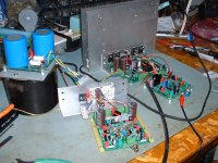
Attachments
Hi All. I have a question that hopefully someone can explain.
In a audio amplifier we have a transformer where the secondary windings are isolated from the primary windings. If each of the secondary windings go through a there own bridge rectifier and form a 0v line. If the 0v line is attached to safety ground if there was a fault and for some reason voltage was to appear on the 0V line would the current then travel to safety ground.
I think not as the secondary side is isolated but I don't know.
Please help me understand this if it does.
Thanks in advance.
Such a fault would mean a breakdown of the isolation, either in the transformer or between the primary and secondary wires to/from the transformer.
The two windings are isolated and independent of each other. (if it is not an autotransformer)
The primary can not close the circuit to the chassis because you would short-circuit the winding and burn the transformer. There circulates the AC current that is "reflected" in one or more secondary windings. The bridge rectifier and capacitors to filter the ripple have one end connected to 0 Volt (ground) but always through a "load", never directly, it would also be another short circuit.
If I understood your question well .......
Attachments
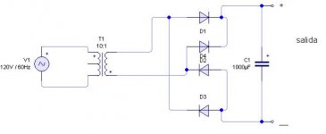

Here you can see the same drawn in a different way, and the load (R) that represents the circuit to be fed with the direct current.
The answer is no. It won't cause a short. If the a center tap of a secondary is grounded, does it cause a short? Same for any leg of the secondary. As long as it one and only one connected to ground.
Hi Guys. Thanks for the responses.Here you can see the same drawn in a different way, and the load (R) that represents the circuit to be fed with the direct current.
With that picture in mind and with the Circuit GND point shown also connected to the Earth Safety Ground point. If the wire leading into the load resistor (The positive) was to short to ground. Assuming that your fuse did not blow would it trigger your safety circuit trip switch in your meter box. That is what I am questioning. Sorry I didn't explain that well enough before.
The answer is no. It won't cause a short. If the a center tap of a secondary is grounded, does it cause a short? Same for any leg of the secondary. As long as it one and only one connected to ground.
Elemental Watson, if two potentials of a different sign (+) and (-) are not joined by a conductor, no current will flow ...
Last edited:
That's what I was thinking. So what is the point then of connecting the 0v rail on the secondary side of the transformer to the chassis which is also connected to Safety Ground. I understand the chassis connection of the Earth wire is there just in case the live wire from the mains comes off and contacts the chassis but what's the point on the 0v connection?Elemental Watson, if two potentials of a different sign (+) and (-) are not joined by a conductor, no current will flow ...
Scott - I don't follow. I believe Stuart is saying the chassis protective earth is in place from the mains ground to the chassis ground point. It's this your protection? What is the need for a connection from the power supply 0V to the protective earth chassis connection.
- Home
- Amplifiers
- Solid State
- How to wire up an Amplifier