The source musical source is never accurate. It is a recording. This recording has nothing (or very few) to do with any reality. It has been produced to be the most agreeable (and sometimes credible) as possible, on the studio monitors that are full of defects and colorations, like all the speakers (as a reference).
What I do not understand is why those objectivists want to impose otherts ("MUST") to cross the united states in the profile racing shell of a pedal car they believe to be a formula one.
Agree with your point of view. But I also think that objectivists have good points. And like in any debate, best view is usually owned by those who understand both points of view. Your view of a shape of an elephant is usually perfect when you understand why blindman1 thinks that it is like a tree, why blindman2 thinks that it is like a spear, etc.
In another thread i discussed about 'niceness' versus 'low THD'. I can't see a reason why i have to sacrifice any of them when they can be achieved altogether. I don't like the sexy sound of (too) dominant low order harmonics, but i also don't like the sound of dominant fifth or seventh.
I often miss the dynamics of real instrument like drums, but i don't want my system to produce more perceived dynamics than what the recording engineer has decided to present. And i can't stand non compressed dynamics of real drums anyway (if my speaker even allowed).
If you know of better ways to reproduce sound, please share.
Accuracy is not about THD only. Even HD is a complex matter that cannot be represented by the standard measurement of THD. Accuracy of an amp is not a matter of how output should be 'similar' with input. A driving stage should have finite or zero output impedance and the preceding stage should have infinite input impedance. This is very underrated, worse if you look at power transfer between amps and speakers. Damping Factor and output impedance of an amplifier are among variables that you cannot compare between input and output. But this will change the sound, make the sound coming out of speakers to be different to what is represented by 1/0 in the recording (or the live sound).
Many subjectivist efforts to 'alter' the sound is probably a form of frustration because of those responsible with knowledge development in this field are not able to present to public a methodology to design audio system that can closely represent the live sound as perceived by the subjectivist good ears.
So I did what JN wanted, though I new the result before testing.
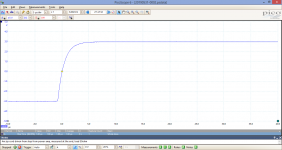
- I took a stable, fool-proof audio power amplifier, with low Zout, no output coil
- I connected 4m of flat speaker zip cord
- I sent a step from the generator to the amp
- I measured at the end of the zip cord, step response. 1st - loaded only by a scope (1M//30pF), 2nd - loaded by a 50 ohm throughput BNC/BNC load
Step responses attached. We may say they are identical, there is no "1us added" in the settling time. There is also no difference of the amp step response with and without the 4m zip cord. -3dB roll off at the amp output is about 140kHz. Further change of load from 50ohm to 100ohm, 20ohm etc. makes no difference in the step response behind the 4m cable.
P.S.: both scope and notebook are battery operated. This is the necessary condition to exclude both ground loops and false signal returns.
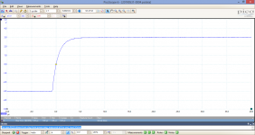
Attachments

Last edited:
For a comparison, 4m of the flat speaker zip cord replaced by 1m of RG58 properly terminated by 50ohm at the end. There is no difference compared to the zip cord measurement. We may say cable properties make no difference in the range of frequencies far behind any audio signal limit. There is no added settling time and no reflections in range up to hundreds of kHz.
JN, I wish you a lot of success in your reflectometry at 10 kHz in 5m of a speaker cable, but please accept my cordial advice - please do not use an oscillating amp or an amp that starts to oscillate with a complex load, like CB did. You may come to false conclusion then 😉
JN, I wish you a lot of success in your reflectometry at 10 kHz in 5m of a speaker cable, but please accept my cordial advice - please do not use an oscillating amp or an amp that starts to oscillate with a complex load, like CB did. You may come to false conclusion then 😉
Attachments
Last edited:
Could you do the same test with a speaker connected please Pavel?
I know that the thread is long, and that it is almost impossible to follow any line, but I did the test with speaker connected few days ago and posted it here. So please list several pages back and you should find it. It was done first with a slower equipment (Tr about 10us) and then with a faster equipment (Tr about 1us). After doing that test with speaker connected, JN asked me to disconnect the speaker and measure just a cable with different resistive loads. I am sorry but connecting a speaker to the end of the cable again has had almost no effect. These plots are stored in my database. I am also afraid that any kind of measurements posted would only rise requirements for new measurements. The reason is understandable, the believers and hypothesis creators are so firmly self-convinced about their thoughts, that they do not accept any experiment that would not support their thoughts. This is fine, but then I ask to do some some job other than endless debates.
So - no, sorry. I have just packed my testing place. I do not see a reason to make further measurement which I already did several times just for the reason to read further complaints and suggestions.
Ok, I'm sorry. I agree, thanks for your patience. It's about time JN put up or shut up 😀
https://www.diyaudio.com/forums/the...wtorch-preamplifier-iii-2036.html#post5805691
https://www.diyaudio.com/forums/the...wtorch-preamplifier-iii-2036.html#post5805691
Last edited:
So, if the two waveforms are 'identical', why is there such noise difference between the two plots ?.Step responses attached. We may say they are identical, there is no "1us added" in the settling time. There is also no difference of the amp step response with and without the 4m zip cord. -3dB roll off at the amp output is about 140kHz. Further change of load from 50ohm to 100ohm, 20ohm etc. makes no difference in the step response behind the 4m cable.
Dan.
One of the contributor of this thread (Rn.M.) was regularly attacked by some "objectivists".Agree with your point of view. But I also think that objectivists have good points. And like in any debate, best view is usually owned by those who understand both points of view.
But he is probably the one of us best equipped with electronic and electro-acoustic measuring instruments. It tells a lot.
Your example about distortion is quite representative of the nunaceous position which, like you, I consider to be the only valid one.
I am refining, at this moment a project of amplifier.
I have the choice between two solutions. The one offering the lowest total distortion rate at 10kHz, but where the harmonic 3 dominates, the other, slightly higher, but it is the harmonic 2 that dominates.
If the difference is audible, how do you know which one gives the best result, if it is not attentive listening? And do I really need to get into ABX protocols to figure out ?
Without these permanent reminders on the order of a supposed self-righteousness, we could perhaps exchange more agreeably and useful our personal experiences and the few conclusions that one or the other of us could draw from their repetitions.
A good example of this exasperation from PMA (which I congratulate for its rigor) here: John Curl's Blowtorch preamplifier part III post5808020
Last edited:
I already posted several links on hams using ordinary speaker cables as antenna feeds, so the above statement is simply wrong. Any zip cord or twisted pair like CAT5 cable has a characteristic impedance.
Sure - I'd try the same trick but its about understanding the cable characteristics in the context of the load. And you can save a few bucks because most times you'd be forced to buy a whole reel of cable and that gets expensive..
Most amplifiers couple to the speaker + cable through an inductor of between 1uH and 3uH (I've seen up to 5uH) which on the higher side is easily the same as the speaker cable inductance. So any notion that you can split the cable to raise L and lower C ignores the fact that the amplifier output L is about the same.
But, the strangest thing in this whole discussion is that the crossover + speaker LCR is orders of magnitude higher than the cable LCR but people are still saying the cable makes a difference. You have to have a pretty junky cable to have an audible difference.
Worse, the sims and the calculations with the load connected say exactly the same things. And even a resistively terminated cable shows no response anomalies right up to about 1 MHz - no reflections, resonances, nothing - just as the rule of thumb that says it will be if the cable length is a small fraction of the signal wavelength.
"Step responses attached. We may say they are identical, there is no "1us added" in the settling time. There is also no difference of the amp step response with and without the 4m zip cord. -3dB roll off at the amp output is about 140kHz. Further change of load from 50ohm to 100ohm, 20ohm etc. makes no difference in the step response behind the 4m cable."
If you sim this, you get the similar results - so measurement seems to confirm theory.
If you sim this, you get the similar results - so measurement seems to confirm theory.
Most amplifiers couple to the speaker + cable through an inductor of between 1uH and 3uH (I've seen up to 5uH) which on the higher side is easily the same as the speaker cable inductance. So any notion that you can split the cable to raise L and lower C ignores the fact that the amplifier output L is about the same.
I would add that this inductance is a good way (if we can feel a difference in listening), to reduce the distortion level of high order harmonics. by the low pass filter that it causes with the C of the cable.
By winding this inductance so many times, I had that in mind throughout this debate, including the fact that this inductor reduces in a larger proportion the possible input of parasitic HF components in the amp, by the feedback loop.
Last edited:
If you sim this, you get the similar results - so measurement seems to confirm theory.
This is so clear and so simple, that measurements and theory cannot be in any contradiction. If they are, I would ask the 1st question - what is wrong with the measurements? One of the answers is oscillating amp that CB used. However faulty equipment results are more attractive than the proper ones.
If you will reduce level of (audible, "If we can feel difference") high order harmonics, you must to supress also usefull part of audioband. You find this good way? I suggest to use better amp as cure..🙄I would add that this inductance is a good way (if we can feel a difference in listening), to reduce the distortion level of high order harmonics. by the low pass filter that it causes with the C of the cable.
Yes, let's talk about sensible things like harmonic (distortion) filters 🙂
ah, he means the higher order harmonics above 400kHz, right.......so what he's really talking about is amplifier stability, good idea
ah, he means the higher order harmonics above 400kHz, right.......so what he's really talking about is amplifier stability, good idea
Last edited:
2.05mm diameter cable with 300 volt PVC insulation of parallel construction. Or just heavy gauge lamp cord.
DX Engineering Zip Cord Power Wire DXE-PW-12 - Free Shipping on Most Orders Over $99 at DX Engineering
Thanks! Perfect.
1µH inductance will set a low pass filter at something like > 400 kHz with most of the speaker cables.If you will reduce level of (audible, "If we can feel difference") high order harmonics, you must to supress also usefull part of audioband. You find this good way? I suggest to use better amp as cure..🙄
Reason why my question: ""if we can feel a difference in listening". I'm never definitive about what we can hear or not.
Last edited:
Thanks. And, I found my vpn was causing gallery images not to show. Sorted now!!
Which is why an ideal system is an active speaker with digital input - optical, wireless, or Ethernet / AES-67.
Exactly!
And just what I'm putting together, sadly rather slowly. Currently art the stage of optically linked monoblocks directly at each speaker - co speker cable about 20cm long, but still have crossovers to get rid of.
Which is exactly what I've been advocating. Lower the RF z, and lower Ls follows with higher capacitance..tomaytoes, tomahtoes..
So, cat 6 cable, with all 4 pairs paralleled, would make good speaker cables? 4 Zo = 100 in parallel and an overall screen is needed?
Exactly!
And just what I'm putting together, sadly rather slowly. Currently art the stage of optically linked monoblocks directly at each speaker - co speker cable about 20cm long, but still have crossovers to get rid of.
Sounds good to me. Lots of challenges and choices to make, but it’s the right approach for perfection. I think wireless can be done but may require custom protocols to allow for low latency and low skew between channels.
Yes, wireless seems overkill to me, though there are some very good dedicated chips for that. But optical is cheap and very effective. Currently using hypex units as the amps, but I have a bunch of TI class D dev boards from their last sale to measure and modify.. 🙂
- Status
- Not open for further replies.
- Home
- Member Areas
- The Lounge
- John Curl's Blowtorch preamplifier part III