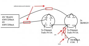
I have been using an old amp of mine that I kept in storage for years. It's a 300B amp with a separate tube rectified supply. No schematics, but it's simple to explain: the filament transformer has five secondaries for the tubes in the amp, the buffer tubes, the 300B's and the rectifiers (5R4). There's a delay for the HV transformer. After the two rectifier tubes I have one 5H coil connected to the filaments of the second tube, then a capacitor bank (450uF), then another 5H coil then another cap bank (450uF). That connects to the O/P transformers on the one hand, and to the buffer 6SN7's tubes (preceded by another 10H coil and 700uF cap bank).
The problem I'm having is with the high inrush current on the filaments when I turn on the amp. Will all tubes I have tried I can see a blue spark inside, about 2 seconds after the amp is on and way before the HV section kicks in. I have tried 5U4's, 5R4wGY (Chatham), 5R4GY (RCA). I have used a pair of the Chatham 5R4WGY for one year with the best sonic results, but after this period the arching inside the tube is getting ugly and I have noticed a decrease in SQ in the last couple of days, which tells me the tubes are going to fail soon.
I have installed a NTC thermistor I had here (Rhopoint SG240) btw the AC and the primary of the filaments transformer, but apparently it's not doing anything, at least I can't tell as the arching is the same. I'm not sure an inrush current limiter can be successfully used here, but that's my best hope as I'm not willing to supply dc to the filaments.
The tubes are expensive and I don't believe this is an acceptable characteristic of the amp, probably the reason I stopped using it many years ago, in spite of great sound.
I thank whoever can help in advance for suggestions.
Last edited:
Member
Joined 2009
Paid Member
It's nearly impossible to generate a blue spark inside a rectifier tube from filament voltage only. This is usually a flash over from plate to filament.
I'm guessing that your HV is on at start up or is starting early, at 2 seconds. Maybe a relay or other switching mechanism has failed?
I'm guessing that your HV is on at start up or is starting early, at 2 seconds. Maybe a relay or other switching mechanism has failed?
I will check the delay tomorrow then. There's some voltage passing through to the HV transformer as there's a 100ohm resistor in parallel with the relay. No idea why that resistor is there, but it might be causing the issue (?)
I don't think the delay is the problem as it does kick in about 10 secs after turning the amp on. It's pretty obvious when it does. Let me know if you think the issue can be the 100ohm resistor.
I don't think the delay is the problem as it does kick in about 10 secs after turning the amp on. It's pretty obvious when it does. Let me know if you think the issue can be the 100ohm resistor.
your description doesn’t make sense to me, a drawing with pin numbers would be helpful.
Attachments
Member
Joined 2009
Paid Member
that 100r resistor provides a soft start, reducing inrush current to the HV primary but it will allow mains to reach the HV transformer primary. Until the amp starts drawing current from the HV supply there will be limited voltage drop across that 100R so you’ll have some HV present at the secondary of the HV transformer before the delay-relay closes. As George says, you need some HV for blue arcs and your HV is ‘on’ at start-up. It takes a Couple of seconds for the rectifier filament to warm up and start conducting which is when you see the blue flash.
some things to try based on what I’ve read about reducing stress on the rectifier, a) add high voltage silicon diodes in series with the plates to protect the tube rectifier from high reverse voltage stress, b) add a small cap to ground after the tube rectifier to shunt high frequency voltage spikes (<1uF), c) increase series resistance to the tube rectifier
some things to try based on what I’ve read about reducing stress on the rectifier, a) add high voltage silicon diodes in series with the plates to protect the tube rectifier from high reverse voltage stress, b) add a small cap to ground after the tube rectifier to shunt high frequency voltage spikes (<1uF), c) increase series resistance to the tube rectifier
Last edited:
Thank you. You mean a small cap before the first coil? I don't quite get "c".
Any suggestion about the arc issue specifically? I wonder if that is more deleterious to the tubes than a "hard HV start". Or you think if I elimiunate the resistor I'll have the arc anyway when the HV starts?
Any suggestion about the arc issue specifically? I wonder if that is more deleterious to the tubes than a "hard HV start". Or you think if I elimiunate the resistor I'll have the arc anyway when the HV starts?
Last edited:
You may have a variety of possible issues. It sounds like this is a diy setup, which makes it easy for us to miss an issue when there is no schematic with a good level of part description and operating levels.
Although choke input filtering was commonly used in vintage days, it can lead to transients at the diode/choke node, which can exacerbate the PIV seen by the diodes as the choke can force a voltage at its node due to any change in current. As such, the addition of a suitably rated small capacitor at that node can suppress the level of voltage transients that could occur (transient levels that can stress diode PIV as well as choke insulation). That capacitor should connect directly to the secondary CT node, as that is the current loop path.
Without a schematic and its details, the addition of ss diodes is uncertain as there is no information on what PIV they need to cope with.
Member
Joined 2009
Paid Member
what trobbins said.I don't quite get "c".
in this case, any kind of arc is bad news, likely means the rectifier is now unrecoverable and certainly worse than a hard HV start - it's my opinion that a soft start for HV is rarely required for a regular tube amp and even more so if you use a 5AR4 indirectly heated type rectifier with has a slow warm upAny suggestion about the arc issue specifically? I wonder if that is more deleterious to the tubes than a "hard HV start". Or you think if I elimiunate the resistor I'll have the arc anyway when the HV starts?
the addition of ss diodes is uncertain as there is no information on what PIV they need to cope with.
This is a 300B amp, so a UF4007's in series with each rectifier plate may be all that's needed to stop the flash over.
This was added to all SSE boards back around 2010 when everybody was turning out junk 5AR4's. If the cathode (or filament) coating isn't even and uniform, or the assembly isn't concentric, the conduction will start at the place where the coating is the thinnest since that spots heats up faster, or at the place where the cathode to plate spacing is the shortest. This poor spot gets to eat all the current being sucked by the hungry empty filter caps. Localized overheating occurs resulting in a flash over.
The diode trick seemed to fix the issue, and the characteristics of the tube dominate over the 0.7 volts of the diode, so the diode doesn't get heard. Even a standard 1N4007 will work. If not, it was a cheap experiment.
likely means the rectifier is now unrecoverable
I have found this to be the case with 5AR4's, once they spark out, they will always spark out. DH rectifiers seem to be able to spark dozens of times before they die.
Last edited:
As is so often the case, we are without a schematic. It sounds like the rectifier feeds the 5H choke, and the 5H choke feeds the 470uF cap, Right? What is the current rating of the 5H choke? Is the choke in saturation when it first attempts to charge the 470uF cap? 100 Ohms current limiting resistor is not enough for some rectifier tubes that have to work into a very large first capacitance value, and have a very high secondary voltage (even if it is a choke input supply). What is the DCR from the center tap to one side of the secondary? What is the RMS voltage from the center tap to one side of the primary? Numbers and Schematics do count. The farmer heard a pheasant fly up out of the field, so he shot off a shotgun (he did not aim, he did not get a pheasant, but he did hit the barn).
Last edited:
what trobbins said.
in this case, any kind of arc is bad news, likely means the rectifier is now unrecoverable and certainly worse than a hard HV start - it's my opinion that a soft start for HV is rarely required for a regular tube amp and even more so if you use a 5AR4 indirectly heated type rectifier with has a slow warm up
Thank you. The tubes I have tried with the amp are 5U4's, 5R4wGY (Chatham), 5R4GY (RCA). I have not used a 5AR4.
I still don't understand your suggestion of adding resistance to the rectifiers...
The comment (c) by Bigun on adding resistance relates to valve diode stress from peak current conduction. It was a group of catch-all comments, and (c) may not relate to your situation as it is a choke input filter configuration, but without a schematic showing part details, it may crop up as a concern. At turn-on, the diode may experience some current pulses with higher peak levels than experienced during normal amp operation - that can particularly be the case if you have turned the power switch off then on fairly quickly, as the diode cathode is hot and so will conduct immediately. The common method of managing peak current level is by winding resistance and sometimes additional resistance.
Can you please check the image? Is that what you mean?This is a 300B amp, so a UF4007's in series with each rectifier plate may be all that's needed to stop the flash over. <snip>
Attachments
I can also eliminate the delay, the 100ohm resistor and the thermistor, and just install a separate switch for the HV, which I'll throw 10 secs or so after the filaments are on. And I could add a first switch for the 100ohm resistor, but with the comments of it not being possibly necessary or being underrated, this might not be the case.
I believe to have described the power supply schematics on the first post and I sent a sketch of the rectifiers config. What other info should I provide?
I believe to have described the power supply schematics on the first post and I sent a sketch of the rectifiers config. What other info should I provide?
Not quite, as the ss diodes are around the wrong way.
Some googling should bring up example schematics, such as:
The Immortal Amplifier Mod
There is no transformer info, no load info, no choke DCR or model info - they all contribute to an understanding of how a power supply may perform.
Some googling should bring up example schematics, such as:
The Immortal Amplifier Mod
There is no transformer info, no load info, no choke DCR or model info - they all contribute to an understanding of how a power supply may perform.
Beware with delay, with a valve rectifier the switch has to be in the 5V heater filament, not HV (plates) side.
It seems there is far more capacitance than needed.
Thank you. There're too many different ideas already. Hard to know which direction to follow.
The delay is installed btw the AC plug and the HV primary.
Not quite, as the ss diodes are around the wrong way.
Some googling should bring up example schematics, such as:
The Immortal Amplifier Mod
Thanks.
It seems there is far more capacitance than needed.
Maybe, but with less capacitance the amp doesn't sound as good. I have doen some tests with this in the past.
There is no transformer info, no load info, no choke DCR or model info - they all contribute to an understanding of how a power supply may perform.
The transformer and choke info on the sketch is what I believe would be present on a schematics. I can measure the choke's DCR later.
The load after the capacitor's bank is more complicated. In any case, the problem at stake also happens when I turn on the PS without the amplifier connected to it.
There is no transformer info, no load info, no choke DCR or model info - they all contribute to an understanding of how a power supply may perform.
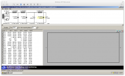
I have found an old simulation I have done for the PS. Please check attached.
I had written on my notes:
"280mA is the DC load of the output tubes' anodes. On the top of that, there is the very high Vac at rectifier frequency (twice mains F) across the choke (see below V (L1) and I (L1)).
Someone suggested that the gap needs to be just right so the sum of Bdc and Bac don't exceed 1.6Tesla, but I have no idea of how to calculate that."
Please take this with a grain of salt...
it's my opinion that a soft start for HV is rarely required for a regular tube amp and even more so if you use a 5AR4 indirectly heated type rectifier with has a slow warm up
So, I have eliminated the delay for the moment and installed a switch for the HV. If I throw the switch 10 or 20 secs after the filaments are on, there's a large arc on both te 5U4 (Harmonix) tubes I have on the PS (these tubes are the least expensive ones I have). The amplifier section is not connected.
If I put the 100ohm resistor there and throw the switch 10/20 secs after the filaments, there's no arc. So I suspect now one solution (not the most practical one though) is to have two switches: one for the 100R, and another for the full power.
I will try the diodes and I will put the small cap there too. But I suspect now the arc is due to the way the PS was conceived, namely with a LOT of capacitance, and I wonder if the diodes or the small cap can do something about that. Will give them a shot though. Apparently there's a safety advantage when using those diodes.
Attachments
If B+ applied when filaments are on and cathodes are hot and emitting, coupling caps between stages charge through grid currents causing anode current peaks of output tubes. It is bad idea to delay B+ in amps. Never do that.
Each rectifier tube is being used in 1/2 wave mode. Each rectifier sees 50 or 60 alternations/sec
Your choke: 5H @ 400mA.
Inductive reactance = 2 x pi x f x L
At 50 Hz, 2 x 3.14 x 50 x 5H = 1570 Ohms
At 60 Hz, 2 x 3.14 x 50 x 5H = 1884 Ohms
The rectifier has a voltage drop, call that 67V. 630Vrms x 1.414 = 891V peak; 891V - 67V = 824V
Admittedly, the rectifier drop will be larger than 67V at peak currents during turn-on transients (but how much more voltage drop?) The 470uF cap that follows the 5H choke is a Dead Short at turn on.
Inrush current at turn on:
50 Hz: 824V peak / 1570 = 525 mA
60 Hz: 824V peak / 1884 = 437 mA
Those inrush currents may saturate your 400mA 5H choke, so 5H becomes 4H, 3H . . . ? With the reduced (saturated) inductance, the inrush current might exceed the rectifier's max peak current spec. Even if the filaments are already warm, when the delayed HV is applied, there will be large inrush currents. Arc, Arc, Arc (perhaps). Only your rectifier knows. Try using a 600mA 5H choke.
Last edited:
Try using a 600mA 5H choke.
For LC-loaded rectifiers it must be so called "Swing-choke", that would not saturate at full voltage swing on the rated frequency. It is huge compared to a choke for CLC filters.
- Status
- Not open for further replies.
- Home
- Amplifiers
- Tubes / Valves
- Inrush current on filaments of tube rectifier?