When using a voltage divider from B+ to elevate heaters is there a preference to where the divider is positioned with respect to the power supply origin? In other words do we put it close to the initial filters so that any AC heater hum leakage is treated by subsequent filter (decoupling) sections or toward the other end (amp input stage) so that the bias voltage has maximum filtering?
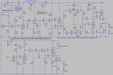
This example shows the latter condition (right above the volume pot in the drawing).
This example shows the latter condition (right above the volume pot in the drawing).
Attachments
for 12ax7 it's about 50v dc...there's no clear rule though, you better use a 1 meg potentiometer and just find the lower noise yourself.It's a balance between the max Vkf and noise...In your case , if you use the first two triodes in the same valve you might have a problem .Usually you place the elevated heater at half the anode voltage when having voltage amplifier-unity gain repeater in the same valve, but you don't need to go beyond the max Vkf so you might probably need to have the first two triodes in different valves supplied from different sources.
You have two channels anyway so you can have each stage of both channels in one valve so that you can use different filament on different secondaries of a transformer floating at any voltage might give you the lowest noise.
You have two channels anyway so you can have each stage of both channels in one valve so that you can use different filament on different secondaries of a transformer floating at any voltage might give you the lowest noise.
Last edited:
OK, I wasn't referring to the bias voltage but rather where to place the divider string as in here at the end or back closer to the power supply (V1).
for the input valves closer to their B+ and tied to own ground , of course...you need it as lower ripple as possible.You can also send two identical 100k...1meg resistors from the divider tap to each sides of the filament so that you have the same vkf potential on the whole filament.
Last edited:
...preference to where the divider is positioned with respect to the power supply origin?...
In *this* case-- your 300r + 100uFd "filter" gives so little filtering, it probably does not matter.
Yes, those are just inter stage decoupling. The bulk of the filtering is already represented in V1. Would you consider the 300Ω-100μf to be adequate for the decoupling? I could make the resistance higher without too much voltage drop.
When using a voltage divider from B+ to elevate heaters is there a preference to where the divider is positioned with respect to the power supply origin?
I prefer to tap it towards the quiet end of the power supply. The elevation supply voltage is itself voltage divided and connected to the center tap (or virtual center tap) of the filament secondary, and the lower resistor in the voltage divider bypassed with say 10 uF or greater, depending on the resistance of the lower voltage divider resistor.
Last edited:
A tuned (ie. pot) humdinger connected to the elevated voltage may still be required to achieve a minimum hum due to heater AC voltage coupling to grid circuitry (either external or internal to tube) via parasitic capacitances.
The elevated DC level of the heater AC makes the heater-cathode leakage resistance look a lot higher that if not elevated, when focusing on typical cathode biased stages (especially unbypassed cathodes as is your input stage, and some of the other stages). It also reduces the heater-cathode voltage stress in the cathode follower stages.
The 270k/47u provides pretty heavy filtering, so I doubt you would notice which B+ node you used, although for sure try not to use a supply to an amp output stage.
I realize this is an old thread, but have a similar question and didn’t want to start a whole new thread.
So this is for a Salas 6V6 preamp that I already built and works great. Just trying to get the noise down a bit more. Currently, I’m showing hum at about -85 dBV. B+ is being regulated by a 21st century Maida. Heaters are brute force rectified and filtered via the 6.3 winding through Schottky diodes and .47R + 110,000uF.
So my question, similar to the OP.
1. Do I place the voltage divider reference at the pre-Maida pre-regulated B+, or do I put it on the clean post-regulated B+ side? Can the CT of the heater winding inject noise into the clean B+?
2. Also, I saw elsewhere that total R should be in the 300k range. I have a 150k and 30k resistor to make the divider- is that sufficient? (500V rated, 1W)
3. Lastly, about the bypass capacitor: I had a 47uF 100v rated cap, I was going to put on the bottom leg of the divider. Somewhere else I saw the cap should be rated for the full HV. Could someone clarify?
Thanks!
Perhaps you need to identify where your hum is coming from first, as elevating the heater may only influence just one of many causes (ie. it just relates to increasing the heater-to-cathode resistance value of the 6V6). Swap in a variety of 6V6 and measure the difference in hum. If there is no change in hum/noise then perhaps start another thread.
Wrt elevation, there is no 'total R' requirement and changing total R won't affect the hum/noise aspect. The cap voltage rating depends on the max level for that location, so if the voltage is lowered due to a divider then it is not exposed to full HV. Given a suitable filter cap value, the origin of the supply should have negligible effect as long as it does not have large AC signal on it.
Wrt elevation, there is no 'total R' requirement and changing total R won't affect the hum/noise aspect. The cap voltage rating depends on the max level for that location, so if the voltage is lowered due to a divider then it is not exposed to full HV. Given a suitable filter cap value, the origin of the supply should have negligible effect as long as it does not have large AC signal on it.
Ok, I might start a new thread later on. Right now I just wanted to specifically ask about the voltage divider location. I was wondering if somehow the CT of the heater winding could inject noise into the very clean post Maida B+.
I swapped in quite a few different types of 6V6s already, and currently in the process of moving a few wires around and cleaning things up. Truthfully, it’s very quiet already, but the OCD in me wants to get the noise down to -100 dBV. It’s good learning experience about the center tap as well. I get the idea- the CT shouldn’t theoretically have noise on it, and the voltage and current only follows +/- around it. But does it fluctuate some in practice?
I swapped in quite a few different types of 6V6s already, and currently in the process of moving a few wires around and cleaning things up. Truthfully, it’s very quiet already, but the OCD in me wants to get the noise down to -100 dBV. It’s good learning experience about the center tap as well. I get the idea- the CT shouldn’t theoretically have noise on it, and the voltage and current only follows +/- around it. But does it fluctuate some in practice?
That preamp doesn't have a heater winding with a CT. If you aren't using the same circuit and pose a query about your circuit then you need to show your circuit.
You identify a -100dBV aim - how are you measuring the noise level and how are you determining if there is any change when tube swapping 6V6's?
You identify a -100dBV aim - how are you measuring the noise level and how are you determining if there is any change when tube swapping 6V6's?
I don’t want to get too into the weeds on this thread- just trying to understand the center tap behavior better, and this little detail about the heater elevation.
I built the gain version and cathode follower version into one enclosure using a dynakit pA060 transformer that I had left over from another project. If you look up my handle and see some posts of mine on that thread, it’s all running quite well.
I just feel that with the Maida and some precautions, I should be able to knock down a bit of noise. I have a quantasylum distortion analyzer which I realize has limitations but good enough for -100 dB work
You seem to be operating in the weeds, which sort of means that many subtleties can be at play, and the only way to appreciate those subtleties is through measurement (assuming you can't hear them). If you have an interface then use that to make some baseline measurements and report them here to show how tube swapping or any particular change to elevation setup has an impact.
Unless you link to a schematic then who knows what you've got.
Unless you link to a schematic then who knows what you've got.
- Home
- Amplifiers
- Tubes / Valves
- Placement of voltage divider for elevated heater