Hello,
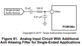
I'm designing a PCM1865 input card and I'm referring to the anti-aliasing filter mentioned in the datasheet like this.

It's calling for something like this:
.01 uF Capacitor = 490-8297-1-ND maybe?
47 OHM resistor = 408-1399-1-ND maybe?
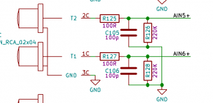
But the FreeDSP Aurora also has an input filter that I've seen, and based my design off of that looks like this.

It has a BOM of this.
100pF = 399-1122-1-ND
100 OHM = RNCP0805FTD100RCT-ND
& an additional resistor = 220k 1% 0.125W Thick
In my design, I sent out to the Fab House with a mixture of these two circuits. I did it by mistake - and probably have some time to change the values if I must. I sent it to the fab house as
100pF = 399-1122-1-ND
100 OHM = RNCP0805FTD100RCT-ND
With no 220k resistor at all.
Yes I'm a newbie.
So, what's the big difference between the caps being 100pF vs .01uF, or the resistors being 47 OHM vs 100 OHM? Will I notice a huge difference in these two filters? Clearly I should have followed the PCM1865 Datasheet and done the .01uF and 47 OHM combination, right? What about that extra 220k resistor on the aurora input board, what's it doing?
I appreciate any insight you might be able to give me. I'm really new and this but I've been able to get pretty far working on this project, I think. The board is turning out very nice otherwise. I just want this to be right. Hopefully it is. Thank you!
I'm designing a PCM1865 input card and I'm referring to the anti-aliasing filter mentioned in the datasheet like this.
It's calling for something like this:
.01 uF Capacitor = 490-8297-1-ND maybe?
47 OHM resistor = 408-1399-1-ND maybe?
But the FreeDSP Aurora also has an input filter that I've seen, and based my design off of that looks like this.
It has a BOM of this.
100pF = 399-1122-1-ND
100 OHM = RNCP0805FTD100RCT-ND
& an additional resistor = 220k 1% 0.125W Thick
In my design, I sent out to the Fab House with a mixture of these two circuits. I did it by mistake - and probably have some time to change the values if I must. I sent it to the fab house as
100pF = 399-1122-1-ND
100 OHM = RNCP0805FTD100RCT-ND
With no 220k resistor at all.
Yes I'm a newbie.
So, what's the big difference between the caps being 100pF vs .01uF, or the resistors being 47 OHM vs 100 OHM? Will I notice a huge difference in these two filters? Clearly I should have followed the PCM1865 Datasheet and done the .01uF and 47 OHM combination, right? What about that extra 220k resistor on the aurora input board, what's it doing?
I appreciate any insight you might be able to give me. I'm really new and this but I've been able to get pretty far working on this project, I think. The board is turning out very nice otherwise. I just want this to be right. Hopefully it is. Thank you!
Attachments
I should have followed the PCM1865 Datasheet and done
the .01uF and 47 OHM combination, right?
Yes, see if you can halt the board fab and fix this.
Do you think that the following choices are a good choice?
.01 uF Capacitor = 490-8297-1-ND maybe?
GRM2195C1H113JA01D Murata Electronics North America | Capacitors | DigiKey
47 OHM resistor = 408-1399-1-ND maybe?
RL1220S-470-F Susumu | Resistors | DigiKey
Thanks for your advice.
.01 uF Capacitor = 490-8297-1-ND maybe?
GRM2195C1H113JA01D Murata Electronics North America | Capacitors | DigiKey
47 OHM resistor = 408-1399-1-ND maybe?
RL1220S-470-F Susumu | Resistors | DigiKey
Thanks for your advice.
Do you think that the following choices are a good choice?
Those should work. The cap is COG/NPO (good), and the resistor is a thin film
current sense resistor, which should be ok.
100pF will do nothing, basically. Those filter values assume the single ended input is low impedance (much lower than 100 ohms), which means they probably assume an opamp output on the same pcb.
With an external signal of unknown impedance your frequency response may no longer be flat in the audio band using just a passive filter.
With an external signal of unknown impedance your frequency response may no longer be flat in the audio band using just a passive filter.
100pF will do nothing, basically. Those filter values assume the single ended input is low impedance (much lower than 100 ohms), which means they probably assume an opamp output on the same pcb.
As pictured, it's an input coming from an RCA connection (external source). Then it is sent TO an opamp that is then fed into the ADC. My connection is different. It is just straight from external source to ADC (PCM1865).
With an external signal of unknown impedance your frequency response may no longer be flat in the audio band using just a passive filter.
OK so then you agree that I need the higher value with .01 uF Capacitor and 47 OHM resistor. Right?
Unfortunately I haven't yet studied all of this in the mathematical sense. I've only been able to put things together by following the Evaluations Module's schematics and BOMs, and from various sources I have found on the web. I'm sure I'm botching this up but I'm hoping that I manage to have a working card in the end.
I'm also hoping to design an input that will work with both balanced and single ended inputs.
Hello Friends,
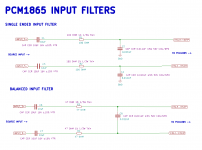
I made a drawling of the two input filters as described by the datasheet on page 74 (http://www.ti.com/lit/ds/symlink/pcm1862.pdf), but I further detailed the "types" of resistors and capacitors that I believe to be true to spec. The datasheet doesn't specify these things so it's been a learning curve.

1. The only change between single ended and differential is the 100 OHM vs 47 OHM serial resistor, and the fact that the pairs are tied together with the .01uF capacitor. I'm just trying to understand it, no real question here.
2. The 10 uF input capacitor is an X7R specification, simply because I'm unable to find a suitable COG/NPO in that size. Is this to spec for a robust input? Any advice on what should be spec'd here instead? I've read about X7R resistors in an audio path being noisy?
3. If I want to keep my module as generic as possible, with the capabilities of balanced and single ended inputs, can I use the single ended input with the anti-aliasing filter? So I would keep the 100 OHM resistor and .01uF cap as shown in the single ended input? Or would I be better off using the balanced input option, and tie the second differential line to ground?
I made a drawling of the two input filters as described by the datasheet on page 74 (http://www.ti.com/lit/ds/symlink/pcm1862.pdf), but I further detailed the "types" of resistors and capacitors that I believe to be true to spec. The datasheet doesn't specify these things so it's been a learning curve.
1. The only change between single ended and differential is the 100 OHM vs 47 OHM serial resistor, and the fact that the pairs are tied together with the .01uF capacitor. I'm just trying to understand it, no real question here.
2. The 10 uF input capacitor is an X7R specification, simply because I'm unable to find a suitable COG/NPO in that size. Is this to spec for a robust input? Any advice on what should be spec'd here instead? I've read about X7R resistors in an audio path being noisy?
3. If I want to keep my module as generic as possible, with the capabilities of balanced and single ended inputs, can I use the single ended input with the anti-aliasing filter? So I would keep the 100 OHM resistor and .01uF cap as shown in the single ended input? Or would I be better off using the balanced input option, and tie the second differential line to ground?
Attachments
So, what's the big difference between the caps being 100pF vs .01uF, or the resistors being 47 OHM vs 100 OHM?
The filter with the 0.01u is an antialiasing filter needed by the DAC.
The filter with the 100p is an EMI filter, working only at very high frequencies, to keep hf junk out.
Two different filters for two different purposes.
Jan
Hi Jan,
Excellent, thank you.
What about the 10uF Capacitor at C2, C3, C5, C7? What does this one do, and are there any specifics in terms of spec's I need to watch out for in order to provide good sound? Do any of the caps have polarity?
The filter with the 0.01u is an antialiasing filter needed by the DAC.
The filter with the 100p is an EMI filter, working only at very high frequencies, to keep hf junk out.
Two different filters for two different purposes.
Excellent, thank you.
What about the 10uF Capacitor at C2, C3, C5, C7? What does this one do, and are there any specifics in terms of spec's I need to watch out for in order to provide good sound? Do any of the caps have polarity?
They filter out any DC component on the input.
Yes, DC blocking capacitor... Thanks!
Do they need to be polar? Is X7R ok for that one?
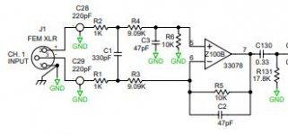
I'm looking at doing something similar for live sound use so hung off 100ft of cable.
The ADC's are the inputs on an ADAU1701 which are non differential but will be using 2 inputs and inverting one in the DSP. I came across the Rane 'Discontinued' schematics
Discontinued Rane Products that may be of interest, these are analogue units, from the Rane AC23B:
The ADC's are the inputs on an ADAU1701 which are non differential but will be using 2 inputs and inverting one in the DSP. I came across the Rane 'Discontinued' schematics
Discontinued Rane Products that may be of interest, these are analogue units, from the Rane AC23B:
Attachments
Yes, DC blocking capacitor... Thanks!
Do they need to be polar? Is X7R ok for that one?
X7R is not great for DC coupling. Better to use a film. Also make sure to have a DC path to gnd after the coupling caps as a just in case footprint.
X7R is not great for DC coupling. Better to use a film.
Hello mlee! Woah film types are expensive. I'm hoping for an SMD 0805 sized capacitor.
Also make sure to have a DC path to gnd after the coupling caps as a just in case footprint.
Is that the "100R to Ground" that I've seen after the "DC Blocking Cap"? Is that what that is about? The 100OHM resistor connected to ground is a backup plan for the DC voltage to go if all else fails?
I'm looking at doing something similar for live sound use so hung off 100ft of cable.
The ADC's are the inputs on an ADAU1701 which are non differential but will be using 2 inputs and inverting one in the DSP.
Hello SubSoniks! Yeah I'm using an ADAU DSP too for this project. Though the board I'm designing is a DAC/ADC board with PCM5242 and PCM1865. Fed via FreeDSP Expansion connector to the FreeDSP Aurora (or otherwsie in the future). I am also doing "live pro audio" and it too will have +/- 100 ft of XLR cables to instruments, mics, and other pro devices. So we are running down a similar path. I've been at this too long and I need a breakthrough. I'm hoping to get this PCM1865 ADC card right the first time (fingers crossed).
But the reason I brought this topic up is highlighted by your post of the Rane Schematic. There are VAST differences in schematics for inputs like this. I'm the type to look for "standards". I'll of course, just go off the datasheet, but I was hoping to stumble upon the "industry standard". Nope, I don't think that exists.
My only real question at this point is what CAP to use for that DC Blocker... Then I'll update my drawling for reference. I can't spend too much on this DC blocker, and I would prefer a 8085 size but I'm willing to compromise. Any advice on a specific part i should consider?
Maybe:
NOJA106M010RWJ AVX Corporation | Capacitors | DigiKey
AVX P/N
NOJA106M010RWJ
film caps of that SMT size won't work.
Any resistor value to GND will work after the DC coupling cap. Sometimes after DC coupling some reference to GND is needed. Good to have a footprint there. Usually it makes up the input impedance of the device.
Another option might be an audio grade electrolytic from panasonic. There was a series of articles that whet though testing of electrolytic caps and I think (don't quote me) that double the value electrolytic and 2 in series measured the best distortion wise for electrolytic. I don't remember the exact particulars but was a 6 or 4 part series.
Ah, that's why the FreeDSP aurora has all those "trash cans" on the board. They are using through hole 20% 25V 100u Caps UVY1E101MDD-ND.
UVY1E101MDD Nichicon | Capacitors | DigiKey
Maybe I can figure out how to fit them into the board. Geez that might be tight. :-/ I guess the Niobium Oxide Capacitors will work too, as per mlee.
UVY1E101MDD Nichicon | Capacitors | DigiKey
Maybe I can figure out how to fit them into the board. Geez that might be tight. :-/ I guess the Niobium Oxide Capacitors will work too, as per mlee.
Why does almost every ADC evaluation module I search for use X7R for the DC blocker??? The PCM1865EVM is using an X7R. Are these suggestions elitist? Or does TI have some special compensation built into the parts? Are we talking same quality specs here? I need good quality, not extremely high quality. Thoughts?
- Status
- Not open for further replies.
- Home
- Source & Line
- Digital Line Level
- ADC input Antialiasing Filter