Dear experts
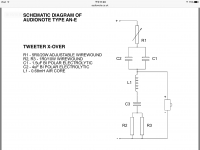
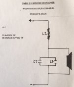
Does anyone know what's the role of the R1 pot in the high pass filter of the crossover? I can see that it's in series with the high pass capacitor. I need to reduce the tweeter amplitude a bit. Can I do so just by adjusting this pot without adding an Lpad?
Does anyone know what's the role of the R1 pot in the high pass filter of the crossover? I can see that it's in series with the high pass capacitor. I need to reduce the tweeter amplitude a bit. Can I do so just by adjusting this pot without adding an Lpad?
Attachments
Last edited:
I need to reduce the tweeter amplitude a bit. Can I do so
just by adjusting this pot without adding an Lpad?
Yes, that's probably what it's for.
And while you are at it, replace C1 and C2 with some nice film caps. 🙂
Right, by now the three bipolars are probably fading.
Thank you all. I'll try to adjust the pot and see what happens.
Re the caps, those are Black Gate bipolar. I measured all of them in both speakers and their capacitance are matched to the second digit left Vs right channel.
Re the caps, those are Black Gate bipolar. I measured all of them in both speakers and their capacitance are matched to the second digit left Vs right channel.
Snell E Crossovers that are similar to Audio Note E Crossovers.
I am interested in upgrading the capacitors, resistors & wire. Erik has mentioned in the past about being careful with ESR when replacing the capacitors. I’m not sure what effect the sliding resistor would have when replacing electrolytics with film caps. Thanks, John
I am interested in upgrading the capacitors, resistors & wire. Erik has mentioned in the past about being careful with ESR when replacing the capacitors. I’m not sure what effect the sliding resistor would have when replacing electrolytics with film caps. Thanks, John
Attachments
-
 73CC36BE-3803-46E2-8F1D-01D6C8899A3B.jpeg802.3 KB · Views: 631
 -
 CBD970E0-51E5-4223-8330-75B6AB841AFB.jpeg721.4 KB · Views: 1,135
 -
 DFD2ECE7-5198-4E4B-9752-D1A05F8A20A1.jpeg692.4 KB · Views: 641
 -
 FDAD38FF-4A73-4CC6-A422-1EF6CE1DB2A5.jpeg48.1 KB · Views: 689
 -
 ED115F45-FA7C-4807-A26A-B36CF167DF80.jpeg69 KB · Views: 853
 -
 FF6CC1C2-6D7F-4F7F-B5F3-372590F7D39A.jpeg595.9 KB · Views: 535
The first image may have an error. The pot is connected as a resistor, and turning it will have no effect.
If you see an electrolytic, and it's bypassed well, it's probably going to have a pretty low ESR already. If the cap is in series with a driver, it's a lot less risk to do something wonky. A little louder, a little softer maybe. So in the first diagram, C1 and C2 are totally easy to replace with high quality film.
It's those large, 1980's era electrolytic bipolar caps that go to ground which will bite you.
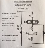
In this case, again, it is C3. If you lower the ESR, you should add to R2/R3 to compensate. In the overall circuit, you could probably screw this up and you'll be OK, because there's plenty of impedance in the circuit already. Worst case scenario you'll create an excessive notch.
But take the case of the second pole in a low pass filter. That is where a large shift in ESR can change the impedance profile, and on anything but the best amps, change the tonal characteristic.
It's those large, 1980's era electrolytic bipolar caps that go to ground which will bite you.
In this case, again, it is C3. If you lower the ESR, you should add to R2/R3 to compensate. In the overall circuit, you could probably screw this up and you'll be OK, because there's plenty of impedance in the circuit already. Worst case scenario you'll create an excessive notch.
But take the case of the second pole in a low pass filter. That is where a large shift in ESR can change the impedance profile, and on anything but the best amps, change the tonal characteristic.
Last edited:
Indeed you should stress the function of the L either.In this case, again, it is C3. If you lower the ESR, you should add to R2/R3 to compensate. In the overall circuit, you could probably screw this up and you'll be OK, because there's plenty of impedance in the circuit already. Worst case scenario you'll create an excessive notch.
For fine tuning the LCR net, the most important component is the L. A few turns more or less will determine the right frequency of intervention, which may vary from tweeter to tweeter, unless they're perfectly matched.
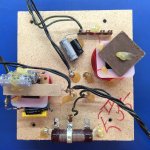
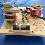
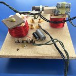
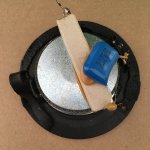
That crossover is a mess. Whose idea was it to stack heat-generating resistors on top of an inductor, then pile around a bunch of cheap electrolytics? It should be totally rebuilt.
Agreed. Appalling!That crossover is a mess. Whose idea was it to stack heat-generating resistors on top of an inductor, then pile around a bunch of cheap electrolytics? It should be totally rebuilt.
Those are the original Snell crossovers. The Audio Note crossovers are similar. I would welcome any advice or suggestions to help rebuild in a better manner.
- Status
- Not open for further replies.
- Home
- Loudspeakers
- Multi-Way
- Audio Note / Snell speaker crossover question