Something to consider/Comments? :
1 kHz Oscillator
I built one last winter and am thrilled with it. It only does 1khz but I am only a neophyte as far as performing testing/measurements.
A schematic is included in the build manual in the link above.
Best,
Anand.
1 kHz Oscillator
I built one last winter and am thrilled with it. It only does 1khz but I am only a neophyte as far as performing testing/measurements.
A schematic is included in the build manual in the link above.
Best,
Anand.
There are a lot of phase shift errors with that schematic.
I prefer less op amps for better linearity.
The formula for working out the frequency is included with the screen shot from Ti.
That TI schematic has no amplitude control and it relies on near-perfect matching between R2C2 and R3C3. Looks quite unpredictable to me.
Hello
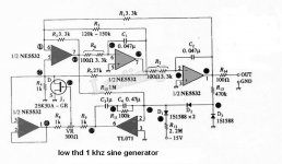
Any opinions or improvements suggestions about this low thd 1 khz sine generator ?
Thank
Bye
Gaetan
It looks like a well-designed two-integrator oscillator. Make sure to use high-Q capacitors: polystyrene, polypropylene or class 1 ceramic (such as NP0/C0G), definitely not MKT or class 2 ceramic. If you need to improve it, you could check whether you can get away with higher values for R3 and R5, use higher-performance op-amps, add current sources to force the op-amp outputs into class A, replace the rectifying diodes with a Pythagorator circuit or try to replace the JFET with a less distorting controlled resistor: LDR and a lamp maybe?
It works fine, I have two of them. THD can be somevere between 0.001..0.010.Any opinions or improvements suggestions about this low thd 1 khz sine generator ?
They are good, if you want to change frequency (R6, R7) - the amplitude will be stable.
A little later I can give some more details about present actual parts (it is at work).
And yes - NP0 are super-good here (C1, C2).
Last edited:
R5, R3 (and R4) - must be as described.
R1, R2, R6, R7 - may vary very wide, they set frequency. (R1, R2 - change amplitude too).
Diodes - 4148 (4448). I usually use R1=R2=R6=R7 - it is convenient.
I forget exact j-fet type I used, but some usual popular one must be ok.
TL071 - TL071 is ok, or other Fet-input opamp.
NE5532 - any dual opamp.
C3 have to be 2 x C4. For low frequencies (tens of Hz) I use larger values - 3u3 and 1u5 low-voltage film caps - it lowers THD by several dB (I used Wima MKT 50 or 63 V).
Last edited:
Hello
I've seen, on the web, the same two-integrator oscillator schematic using LME49720 to replace the NE5532, it have a distortion of .00064 %
I don't have the LME49720, but I have the LM4562
Bye
Gaetan
I've seen, on the web, the same two-integrator oscillator schematic using LME49720 to replace the NE5532, it have a distortion of .00064 %
I don't have the LME49720, but I have the LM4562
Bye
Gaetan
Last edited:
Are you shure it was 0.00064% - but not 0.0064%?, it have a distortion of .00064 %
0.006% is easy achievable by this gen, but one more zero - isn't so easy.
Last edited:
Hello
Yes it was 0.00064%
Bye
Gaetan
What modification it need in the schematic to replace the JFET control by a 1869d lamp ?
Thank
Bye
Gaetan
Yes it was 0.00064%
Bye
Gaetan
HelloIt looks like a well-designed two-integrator oscillator. Make sure to use high-Q capacitors: polystyrene, polypropylene or class 1 ceramic (such as NP0/C0G), definitely not MKT or class 2 ceramic. If you need to improve it, you could check whether you can get away with higher values for R3 and R5, use higher-performance op-amps, add current sources to force the op-amp outputs into class A, replace the rectifying diodes with a Pythagorator circuit or try to replace the JFET with a less distorting controlled resistor: LDR and a lamp maybe?
What modification it need in the schematic to replace the JFET control by a 1869d lamp ?
Thank
Bye
Gaetan
Just add to my previous info:
J-FET I used - 2N5484 (usual popular N-CHANNEL JFET).
It works well as is. It will lose rigidity, I think. And it will have problems with low frequencies with a lamp.
I may be wrong, but oscillators of that type (RC-type or integrator-type), in general, can work fine without amplitude control (regulation) circuits at all.
J-FET I used - 2N5484 (usual popular N-CHANNEL JFET).
- but why? 😱 😕hat modification it needs in the schematic to replace the JFET control by a 1869d lamp?
It works well as is. It will lose rigidity, I think. And it will have problems with low frequencies with a lamp.
I may be wrong, but oscillators of that type (RC-type or integrator-type), in general, can work fine without amplitude control (regulation) circuits at all.
Hello
Because MarcelvdG said that LDR and lamp control are less distorting than JFET control.
Thank
Bye
Gaetan
Because MarcelvdG said that LDR and lamp control are less distorting than JFET control.
Thank
Bye
Gaetan
I was just listing everything I could think of, in a kind of brainstorming mode. I haven't got a concrete circuit proposal for a lamp-and-LDR control.
The basic idea would be to let the TL071 control some sort of lamp driver, maybe just an emitter follower than controls the lamp. J1 then has to be replaced with the LDR, and the lamp and LDR have to be put in some enclosure that ensures that only the lamp shines on the LDR. The C3-C4-R11 network has to be redimensioned because of the changed loopgain and because of the slowness of the lamp and the LDR. This will require some experimentation to get things stable. R8 and the voltage follower on the bottom left of the picture would not be needed anymore.
The basic idea would be to let the TL071 control some sort of lamp driver, maybe just an emitter follower than controls the lamp. J1 then has to be replaced with the LDR, and the lamp and LDR have to be put in some enclosure that ensures that only the lamp shines on the LDR. The C3-C4-R11 network has to be redimensioned because of the changed loopgain and because of the slowness of the lamp and the LDR. This will require some experimentation to get things stable. R8 and the voltage follower on the bottom left of the picture would not be needed anymore.
A simpler modification would be to increase both R3 and R5 by some factor and to increase R11 with the square root of that factor. With increasing factor, the contribution of the JFET to the distortion will decrease, until you make the factor too high, the amplitude control fails altogether and either the distortion goes through the roof or the oscillator doesn't start anymore. The better the capacitors and op-amps, the higher the factor you can get away with.
Last edited:
For the ultimate: http://www.janascard.cz/PDF/An ultra low distortion oscillator with THD below -140 dB.pdf
(though I can't personally vouch for it, although I have thought about building it).
(though I can't personally vouch for it, although I have thought about building it).
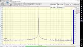
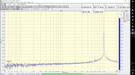
What FFT window are you using for thos measurements? Is that really phase noise or a poor choice of window. Ultra high dynamic range flat-top windows are needed for this sort of signal, as the peak has to be straight sided down to -140dB or so to see into the oscillator phase noise.My generator by Viktor's schema
This is one case where the Hann window isn't a sensible choice.
- Status
- Not open for further replies.
- Home
- Design & Build
- Equipment & Tools
- Any opinions or improvements suggestions for this low THD 1kHz sine generator?