as I said in this post https://www.diyaudio.com/forums/digital-line-level/314935-es9038q2m-board-438.html#post5778058 shorted AP's inputs has about .5uVRMS A-weighted i.e. better than -135dbA.may be working at the very low end of its range
...AP's inputs has about .5uVRMS A-weighted i.e. better than -135dbA.
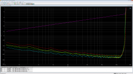
Displayed all in one range or in switched ranges (automatic relays, or otherwise)?
the same and rising noise sometimes it is my wireless mouse activity, all of that stuff(Smartphone/AP/DUT/mouse) on the same desk.
Last edited:
Today I tried to create a PCB for AVCC. LTC6655 + LME OP AMP. I tried to arrange the components as close as possible to each other. Maybe someone has wishes, how to do better. The printed circuit board will be 0.3-0.5mm thin fiberglass, which will allow to place it as close as possible to the ground on the back of the board.

Today I tried to create a PCB for AVCC. LTC6655 + LME OP AMP. I tried to arrange the components as close as possible to each other.
It would be recommended if making an AVCC PCB to make a ground plane on one side and use it for all grounds. Also, the AVCC ground plane should be soldered directly to the dac board ground plane. It would also be very much recommended to do the same for an output stage board. Keeping ground impedance as low as possible is important for best performance. Please see pictures of recommended AVCC board construction in the thread. https://www.diyaudio.com/forums/digital-line-level/314935-es9038q2m-board-278.html#post5554396
Last edited:
It would be recommended if making an AVCC PCB to make a ground plane on one side and use it for all grounds. Also, the AVCC ground plane should be soldered directly to the dac board ground plane. It would also be very much recommended to do the same for an output stage board. Keeping ground impedance as low as possible is important for best performance. Please see pictures of recommended AVCC board construction in the thread. https://www.diyaudio.com/forums/digital-line-level/314935-es9038q2m-board-278.html#post5554396
I got 2 lanes of ground. Otherwise, I can not do it, because the board will be one-sided. I want to make a lot of connection points to provide good ground. Or maybe with the help of copper foil.
Or is it better to make around one big loop of ground?

Or maybe with the help of copper foil.
Perhaps best to attach copper foil to the back side of the board and run all grounds to it using the shortest path possible. In most cases the shortest path would likely require making a hole through the board.
Hah, my Performance-mode looks the same or even worse than Normal-mode on the AP THD+N power sweep plot but harmonics distributions in the Normal-mode is not so clean if not say awful 
Attachments
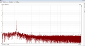
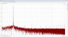
...Performance-mode looks the same or even worse than Normal-mode...
What circuit and or configuration differences are you calling 'normal' and 'performance' modes?
normal-mode is pretty much default registers setting, performance-mode continuously scanning for the sample rate and accordingly modifies registers for optimal THD(THD+N almost doesn't change), and SE-mode adds a lot of 2md harmonic.
...performance-mode continuously scanning for the sample rate...
Optimal HD compensation settings my vary with sample rate.
Typically, whatever USB to I2S chip is used can be programmed to indicate incoming music file sample rate to the MCU and dac. There should be no need to scan for it, unless there is something I am missing here.
Not sure if I understand what you wanna say? MCU scanning means polling registers for the current Fs value to update DAC's registers accordingly for better THD. If I'll stop that polling how I should update registers?
If I'll stop that polling how I should update registers?
XMOS USB to I2S chips have pins that can be programmed to tell which clock family (44kHz or 48kHz) the incoming audio is, whether it is DSD or PCM (DSD_ON), and the sample rate (F0/F1/F2/F3). A change in any of those signals from the XMOS chip could generate an interrupt in the MCU, which could then adjust the dac registers as needed. Or, DPLL_NUM could be polled, as could DSD vs PCM status, but polling is inefficient.
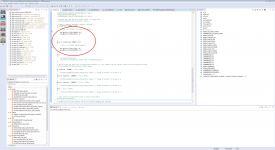
1) XMOS USB to I2S chips is actually normal ARM MCU, and any GPIO behavior only up to me, see attached how I manage OSC exchange according to Fs 😉 The same way I can manage registers updating without any extra pins and interrupts, and I do that.
2) My #9038S isn't XMOS based, and I have there host MCU 3x3mm QFN, any extra GPIOs and PCB tracks are highly unwilled due to PCB size 46x20mm.
3) The MCU isn't busy at all rather idle and may scan Fs inefficiently because nobody care if every 500mS MCU wakes up for few I2C transactions and eats 3mA
Attachments
...host MCU 3x3mm QFN, any extra GPIOs and PCB tracks are highly unwilled due to PCB size 46x20mm...
Okay, thank you. That's what I was asking about.
Now that we understand a little more about what you are doing, may I ask how does it sound if playing, say, 16/44 CD recordings, in performance mode? Have you compared it with any reference dac, or other dacs we might be familiar with?
I'm a normal engineer, I solving technical tasks, that's it. Let see what pro-reviewers will say about it but my tech specs at least 10x times better vs others USB->DAC->HPA dongles what I found on the market 😉
No, my regs has no global negative feedbackNazar regulators use a lot of feedback to keep impedance low
No, my regs has no global negative feedback
But they can oscillate depending on the load. Oscillators require feedback to work, whether it is intentional feedback or not.
That being said, nice to meet you. Any interest in high performance dacs?
If my reg oscillate - it means poor pcb design and not correct output cap properties (capacitance, ESL, ESR).But they can oscillate depending on the load.
my whole conscious life🙂Any interest in high performance dacs?
If my reg oscillate - it means poor pcb design and not correct output cap properties (capacitance, ESL, ESR).
Exactly. Too much phase shift in the feedback loop. 🙂
my whole conscious life🙂
Don't know if you have been following this thread. The 2nd dac I have built is now rated by some listeners (including professional high end audio designer) as having preferred sound quality over Benchmark DAC-3. Roughly speaking, that might put its sound quality at a level commensurate with the Stereophile A+ recommended dacs. Recommended Components: 2019 Edition Digital Processors | Stereophile.com ...It has not been simple to get to that kind of performance level, and I still have more work to do to simplify some of the circuitry (if I can).
- Home
- Source & Line
- Digital Line Level
- ES9038Q2M Board