Hello,
I have a problem with my amplifier it's a Kicker ZX 750, I already change the K1 power relay several times.
I wanted to avoid its destruction by adding a free-wheeling diode, but since then it has stopped working. The relay is no longer active, even with a new one.
I control all the transistors and they are good.
Hello,
I have a problem with my amplifier it's a Kicker ZX 750, I already change the K1 power relay several times.
I wanted to avoid its destruction by adding a free-wheeling diode, but since then it has stopped working. The relay is no longer active, even with a new one.
I control all the transistors and they are good.
What transistors are you referring to in your previous comment? Use locators when referring to parts.
What do you mean by free wheeling diode? There is a diode across the relay coil that will protect the relay, and no other circuitry is necessary.
There is most likely an issue in the turn on/ soft start circuit. When I have a few minutes I will post the relevant locators for the circuit.
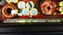
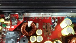
In the meantime post pics of the board. One overall and one tight shot of the relay and surrounding area and another with a tight shot of the TL494 PWM chip and surrounding area.
I was in a hurry earlier and neglected to ask a few questions.
Does the amp power on? Do you have Rails?
Is the issue you have No Output?
If the issue is No Output the issue is as I suggested in my previous post.
It may also be an open via. There may be signs of moisture around the relay, usually you will see it around or under the relay. The trace from the relay turn on circuit if I'm not mistaken runs underneath the Transformer and a connected via may have corroded due to moisture.
What transistors are you referring to in your previous comment? Use locators when referring to parts.
What do you mean by free wheeling diode? There is a diode across the relay coil that will protect the relay, and no other circuitry is necessary.
There is most likely an issue in the turn on/ soft start circuit. When I have a few minutes I will post the relevant locators for the circuit.
In the meantime post pics of the board. One overall and one tight shot of the relay and surrounding area and another with a tight shot of the TL494 PWM chip and surrounding area.
Hello,
Thank you for your answer and sorry for the delay.
The transistors I am referring to are the ones on the side (R0207, R209, R211...)
When I replaced the relay I added a diode on the command. And it is this change that destroyed the amplifier.
I also specify that the relay is different than the original but the characteristics are similar. That's why I added some wires to install it.
The amp turns on but the relay is not controlled.

I was in a hurry earlier and neglected to ask a few questions.
Does the amp power on? Do you have Rails?
Is the issue you have No Output?
If the issue is No Output the issue is as I suggested in my previous post.
It may also be an open via. There may be signs of moisture around the relay, usually you will see it around or under the relay. The trace from the relay turn on circuit if I'm not mistaken runs underneath the Transformer and a connected via may have corroded due to moisture.
Hello PapaZBill,
Do you have a schematic of this ampli?
Thank you
I afraid I can't give out schematics for proprietary reasons. I've got a lot going on right now and won't be able to address anymore questions for a few days.
Do you still have the original relay, and have you determined if it is damaged?
Do you still have the original relay, and have you determined if it is damaged?
I afraid I can't give out schematics for proprietary reasons. I've got a lot going on right now and won't be able to address anymore questions for a few days.
Do you still have the original relay, and have you determined if it is damaged?
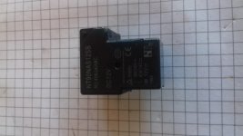
Yes I still have the relay.
I tried it by sending 12V to the command but it doesn't woark anymore.
I will send a picture later.
Ispecify that the relay I mounted, has been replaced 3 times.
That's why I added the diode on the relay control to protect the coil.
But I should never have done it.
Yes I still have the relay.
I tried it by sending 12V to the command but it doesn't woark anymore.
I will send a picture later.
Ispecify that the relay I mounted, has been replaced 3 times.
That's why I added the diode on the relay control to protect the coil.
But I should never have done it.
I would especially like to know where the relay control circuit starts to check the components that match it.
Thank you
Is the relay coil burning open?
How is the relay failing?
I doesn't think so because it didn't explode or smoke.
But when I send the tension on the command, I doesn't hear the clack!. And I check with the multimeter if the contacts change position and they doesn't change.
Last edited:
What's the resistance across the coils of the relays that failed (out of the circuit)?
There is nos value, the good relay has 176 ohm.
I afraid I can't give out schematics for proprietary reasons. I've got a lot going on right now and won't be able to address anymore questions for a few days.
Do you still have the original relay, and have you determined if it is damaged?
Attachments
This amp should have a daughter board for the soft start circuit which includes Q75-KTC3875GR the Relay Turn on transistor. This is mounted on the side of PCB with the power terminals.
Once you've answered Perry's question and determined if the relay is good or bad, you can check the the relay turn on circuit.
This does not require that a relay be installed. After power up Check the DC voltage on either side of D92-LL4004, this diode is across the relay coil.Black probe on Power Ground.The cathode side will read the battery terminal voltage ~12volts. The anode side should read low, maybe .6 volts. If the anode stays high, you have a an issue in the soft start circuit or relay turn on circuit or open trace or via.
I just wanted to know how they were failing. If the coils are opening repeatedly, there may be an intermittent short circuit to higher voltage.
This amp should have a daughter board for the soft start circuit which includes Q75-KTC3875GR the Relay Turn on transistor. This is mounted on the side of PCB with the power terminals.
Once you've answered Perry's question and determined if the relay is good or bad, you can check the the relay turn on circuit.
This does not require that a relay be installed. After power up Check the DC voltage on either side of D92-LL4004, this diode is across the relay coil.Black probe on Power Ground.The cathode side will read the battery terminal voltage ~12volts. The anode side should read low, maybe .6 volts. If the anode stays high, you have a an issue in the soft start circuit or relay turn on circuit or open trace or via.
Where is Q75? I have send a picture.
I have check the DC voltage on either side of D92, the cathode side Il read 12,36 V and the anode side 11,86 V. Bad News?
Thank you for your help.
Attachments
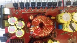
Where is Q75? I have send a picture.
The vertical board is not in the photo. You will find it on the on the other side of the input inductor that is pictured
The vertical board is not in the photo. You will find it on the on the other side of the input inductor that is pictured
I have check the DC voltage on either side of D92, the cathode side Il read 12,36 V and the anode side 11,86 V. Bad News?
The voltages indicate that the relay is not being activated. The possibilities are as I mentioned in a previous post, including a bad Q75 or soft start problem.
The voltages indicate that the relay is not being activated. The possibilities are as I mentioned in a previous post, including a bad Q75 or soft start problem.
- Status
- Not open for further replies.
- Home
- General Interest
- Car Audio
- Kicker ZX750 doesn't work