A little research showed that a non-slew limited VFA was published by Hearn in 1970, is this current mode?
(citation)
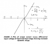
Since I am intimidated by the big bad Four Letter Journal Publisher and their copyright enforcement soldiers, I will show only two figures of that paper and claim Fair Use.
_
Attachments
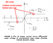
I like it when there are no values on the y-axis, just where it counts. 🙁
Can't comment on the paper otherwise, it's behind the IEEE wall of shame.
regards, Gerhard
my bad will interpretation: 🙂
Can't comment on the paper otherwise, it's behind the IEEE wall of shame.
regards, Gerhard
my bad will interpretation: 🙂
Attachments

Last edited:
I would like to add, at the destination of Dadod, that, despite or because its work is the exact opposite of my natural inclination (Simple is beautiful) he has all my deep admiration: I feel totally unable to achieve such an astonishing thing.
As all my personal efforts consist to optimize the relative gains of current or voltage of each stage (once individually optimized), in order to reduce the overall distortion, and because it is enough so much work with few parameters, how to do-it with so many variables interacting with each others?
[edit]Why the hell am-I so serious, this morning ?
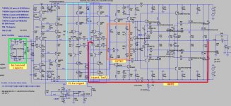
It is not so complicated. Attached schematic with some explanation.
If this amp is CFA there is no H-bridged and input buffer parts(cold input). There is six CCSs and the rest is quite simple amp. 😀
Damir
Attachments
I will show only two figures of that paper and claim Fair Use.
This of course is essentially the same behavior as an H-bridge input VFA. Bob Meyer saw fit to republish it in one of the IEEE "historical" paper collections. This was not hidden knowledge. I expect a fairly decent PA could have been built around these ideas with mid-70's discretes, it would even probably have had low open-loop BW 🙂. Of course WE didn't know about slew rate back then.
Last edited:
maybe you can take this post as a reaction:That I tried to timidly suggest with this little schema presented as a joke:
But nobody reacted.
https://www.diyaudio.com/forums/the...wtorch-preamplifier-iii-1782.html#post5774842
Especially the Holman design where the bipolar trz is in total control of the input j-fet speed, but it's difficult to judge because of the riaa network
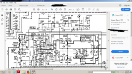
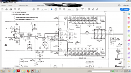
In the first picture attached you will see the best (in my opinion) audiophile design a company ever produced for the money and in the second, the lowest part count and most reliable design for higher power in class ab for touring all over the world. Most probably you all enjoyed the second sound at some point.
Attachments
Last edited:
Well don't you like unbiased opinions , just pure technical reactions like...this is a BS topology or , i couldn't live with so much VFB 🙂 ? If i give the people's name who built the first amp they might suddenly become silent.
We seem to be talking about 3 separate (but related) circuit types.
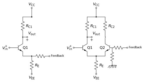
First, VFB is what most typical op amps use, and it can be fast, but usually it is not, because it has too much input transconductance. Only resistors added to the input emitters (or sources) will speed it up significantly. The only other way is increased Gain-bandwidth.
Second, CFB which has been around since the 1930's with tubes and then used with early transistor circuits in the '60's, which has a small advantage of having a BUILT-IN transconductance reducing resistor, nominally the feedback resistor to ground. This circuit can be difficult to bias (especially transistors), but can be pretty fast, especially in one direction, because the input current is not limited by the added differential transistor that turns off when the input turns on, and ultimately 'starves' the input. In this case you HAVE to use an emitter (source) feedback resistor to ground, and this speeds things up accordingly, because less compensation is needed to keep it stable, AND this also can linearize the input stage.
Then there is CMA or current mode feedback.
This is what Richard started with, but he later reverted to CFB in his later designs.
To have CMA you have to have some elegant way to add an input diode to track the exponential input of both the input and the second stage. This linearizes the inputs of each device, and removes the voltage characteristics from the transfer function.
For example, Richards very first example with a diode load is CMA, but his subsequent complementary jfet input used a resistive load and therefore is CFB.
I will stand corrected if I got it wrong.
To have CMA you have to have some elegant way to add an input diode to track the exponential input of both the input and the second stage. This linearizes the inputs of each device, and removes the voltage characteristics from the transfer function.
I will stand corrected if I got it wrong.
This describes forward error correction like cascomp which IIRC was used by Tek in their open-loop deflection amplifiers. Since every scope (used to) come with full schematics I consider it also openly published.
Another major class of CMA amplifiers were the first generation instrumentation amplifiers. First published in 1970 by my old friend Heinrich Crabbe RIP (the remnants of Micropower eventually turned into Linear Systems). These used local feedback to make ideal transconductances, similar to using CFP's as input devices. Rudy van de Plassche published a circuit in 1973 where he used the term current feedback explicitly to describe it in a way I don't think anyone would argue about.
Last edited:
Well...I spent a few minutes reading back about three pages of comments and what was interesting was that in fact this is just another case of faithful disciple that is revering its rightful master up to a point where he becomes irrational attacking all his opponents as the most dangerous people in the universe.
I'm sorry to say that, but here we have just another case of religious electrons.
But you've passed a judgement based on the "cover" of a "book". I'm sure you wouldn't like it if someone does that to you.I don't have the patience for that.I didn't put a blame on anybody .I did the same with many people over the time...We're human nature...
I don't totally agree, John.We seem to be talking about 3 separate (but related) circuit types.
First, VFB is what most typical op amps use, and it can be fast, but usually it is not, because it has too much input transconductance. Only resistors added to the input emitters (or sources) will speed it up significantly. The only other way is increased Gain-bandwidth.
Everything (in my opinion, that has no more value than to be mine) rely on the parasitic capacitance of the input transistors. the ones in the feedback loop.
Increase the feedback impedance in a CFA, and you can see its bandwidth reduced. Decrease the one of a VFA, and you will see its bandwidth increased, until the point it has no more influence in regard of the parasitic capacitance i'm talking about.
The usual problem is, in a VFA, we want to keep +input and - input at the same impedance (you know the reasons).
10K, usually for a power amp.
At this value, the low pass filter in the feedback signal is at work, with the phase turns it produce.
In a CFA, there is no problem (apart dissipation in the feedback resistances and load to the output) to reduce the impedance as much as we need.
Please, note than, adding a capacitance in // with the serial feedback resistance in a VFA helps to increase the stability, because it compensate this phase turn. In a CFA with no phase turn in the feedback signal, it create a phase turn, the bad sens, leading to oscillation.
Hoping my words are clear enough, despite my poor English. What i try to enlighten explain too the differences in the behavior of the two types of topologies, between small an big signals: the parasitic capacitance vary with level.
Last edited:
Well...it actually was in your favor . Maybe if i'd be reading more pages I'd turn against you 🙂But you've passed a judgement based on the "cover" of a "book". I'm sure you wouldn't like it if someone does that to you.
Anyway i thank you for considering my opinions...I've learned in life that my opinions are the most likely ones to be disconsidered .Just do it and you'll be ok with the rest.
If I could afford a house with a playroom for the kids+TV then the living room would become exactly that, but for two up listening. Two's company. Three needs a visit to the doctor 😛
Ha ha
Wife wanted 3 or 4. I went to the doctor and headed her off at the pass 😀
I've learned in life that the best thing to do when you find a foot-in-mouth is to bite it down and endure the pain, not open it wider and push it in further.Well...it actually was in your favor . Maybe if i'd be reading more pages I'd turn against you 🙂
Anyway i thank you for considering my opinions...I've learned in life that my opinions are the most likely ones to be disconsidered .Just do it and you'll be ok with the rest.
Is Goop hi-end?
Depends on who’s producing the Goop. The most hi-end is the Klingon Gagh.
We seem to be talking about 3 separate (but related) circuit types.
.
Then there is CMA or current mode feedback.
This is what Richard started with, but he later reverted to CFB in his later designs.
To have CMA you have to have some elegant way to add an input diode to track the exponential input of both the input and the second stage. This linearizes the inputs of each device, and removes the voltage characteristics from the transfer function.
For example, Richards very first example with a diode load is CMA, but his subsequent complementary jfet input used a resistive load and therefore is CFB.
I will stand corrected if I got it wrong.
That is basically correct, John. The original prototype, operating as CMA measured a Tr of 20 nS. BUT, that was the same as the generator Tr. Knowing the transistors used, the BW was something like 100MHz or greater.
The headphone amp using similar topology but higher Z's and lower input current/SR manages 5 MHz BW
Audiophiles cannot tell easily by looking at a schematic ----> Thus some of the confusion, perhaps between CFB and CMA. But measurments will tell.
CMA has to meet this criteria --->
" Internally compensated VFA bandwidth is dominated by an internal dominant pole compensation capacitor, resulting in a constant gain/bandwidth limitation. CMAs also have a dominant pole compensation capacitor, but due to using current feedback instead of voltage feedback, the resulting open loop response is different. VFA stability depends on the ratio of open loop gain to feedback gain; CMA stability depends on the ratio of open loop transimpedance to feedback resistance. VFAs have a gain/bandwidth dependence; CMAs have a transimpedance/feedback resistance dependence."
Keeping it simple: If your BW is independant of the gain set, it likely is operating CMA. 🙂 If your amp's BW changes with the gain set, it is likely VFA.
THx-RNMarsh
Last edited:
- Status
- Not open for further replies.
- Home
- Member Areas
- The Lounge
- John Curl's Blowtorch preamplifier part III