Thanks again for all that guy's. Just wondering if anyone has upgraded there output stage to a triple EF. There seams to be a lot of advantages to having a triple. No idea why the HD does not employ one.
i have a badger TEF in the works, the VAS and the big CCS are adjusted for 5 mA idle currents....
Awesome. Do you have any photos and a schematic showing how you wired in the pre drivers. What transistors did you use?i have a badger TEF in the works, the VAS and the big CCS are adjusted for 5 mA idle currents....
will post pics once i have them...
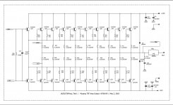
Wow, Tony the way you have layed out that schematic is really neat and is so easy to follow. I like how you have added some over current protection as well.
So nice.
Have you started a thread for this Mustang TEF?
One thing I noticed and its probably just how you have done the schematic the FBK is been taken from slightly the wrong point.
I read this in Douglas Self Book Chapter 5 and 11.
I have placed it in the location that he recommends. No sure if you agree.
Keep up the good work and I look forward to reading more about this. 🙂
Attachments
Last edited:
Wow, Tony the way you have layed out that schematic is really neat and is so easy to follow. I like how you have added some over current protection as well.
So nice.
Have you started a thread for this Mustang TEF?
One thing I noticed and its probably just how you have done the schematic the FBK is been taken from slightly the wrong point.
I read this in Douglas Self Book Chapter 5 and 11.
I have placed it in the location that he recommends. No sure if you agree.
Keep up the good work and I look forward to reading more about this. 🙂
we call it the "Musang" amp, a local specie of the badger....
all the work was done by a Pinoy xerox engineer from the middle east...
board fabrication is by another friend from Shenzhen in china...
no, i am not officially sharing it in this board, sorry...
i would say many inputs on layout was also taken from here...
not sure what you mean, i have not read Self that much, right now i amp happy with this layout...though i still have a long ways to go, to come up with a working amp...
the schematic as drawn and the actual board layout are quite different, this i can assure you...
even the placement of the protection sensing resistors are such that removing them later in is quite easy...
Hi Tony. As I said before this layout looks amazing. I understand that you are not able too share it. But I was wondering if you could possibly pass on some details.will post pics once i have them...
Will the pcb be eventually available for sale?
What is the size of the pcb?
What is that round silver looking thing below the transistor labels on the silkscreen Q22, Q24 and Q26 for example? Is this just the top view of a pcb stand off?
Hi Tony. As I said before this layout looks amazing. I understand that you are not able too share it. But I was wondering if you could possibly pass on some details.
Will the pcb be eventually available for sale?
What is the size of the pcb?
What is that round silver looking thing below the transistor labels on the silkscreen Q22, Q24 and Q26 for example? Is this just the top view of a pcb stand off?
this TEF is a spin off the 10 pair darlington badger we did earlier , we have verified the board and it works...yes, those are supposed to be mounted on heatsinks and so are located under the board...
the TEF version has only 9 pairs output, the other pair used as drivers to the other 9 pair..
pcb is 15 inches x 4 inches and is 2 mm thick, 2 oz copper, we have 10 boards made...i would rather have this as 2.6 mm thick board...
i have a Conrad engineering 35cm x 15 cm which is a bit short, so i am thinking of 4 pcs 25 cm ones to use here...
this board will be available at Lazada in the near ffuture..
Thanks for the update Tony.this TEF is a spin off the 10 pair darlington badger we did earlier , we have verified the board and it works...yes, those are supposed to be mounted on heatsinks and so are located under the board...
the TEF version has only 9 pairs output, the other pair used as drivers to the other 9 pair..
pcb is 15 inches x 4 inches and is 2 mm thick, 2 oz copper, we have 10 boards made...i would rather have this as 2.6 mm thick board...
i have a Conrad engineering 35cm x 15 cm which is a bit short, so i am thinking of 4 pcs 25 cm ones to use here...
this board will be available at Lazada in the near ffuture..
I think the whole PCB has been well thought out.
I am interested to see the bottom of board so I can see how to MFB trace is routed. Do you have a similar image showing the underside?
Speaking with not alot of experience I was also wondering why the same transistors are being used as the drivers running in class A. Q18 2CS5200 and Q19 2SA1943 As the beta of those transistors are A lot lower (160) then say a the 2SC3503 and 2SA1381 which have a gain of up to 320. I was thinking that the transistors that I just mentioned could be used as the pre-drivers and the current transistors Q16 & Q17 could possibly be used as the main drivers.
Like I said this is just a question not A criticism of this awesome layout.
I will keep my eye out for the pcb's.
Requested by Mr. Andrew Lebon to be posted.
Musang Amp Ver 8.1 all files as posted by Mr. Arnel Rabang in March 11, 2017.
Musang Amp Ver 8.1 all files as posted by Mr. Arnel Rabang in March 11, 2017.
Attachments
-
Musang Amp Ver 8.1_drillhole.pdf8.9 KB · Views: 110
-
Musang Amp Ver 8.1_sch.pdf52 KB · Views: 148
-
Musang Amp Ver 8.1_pcb ntr mthd.pdf80.4 KB · Views: 103
-
Musang Amp Ver 8.1_pcb cttng mthd.pdf80.6 KB · Views: 108
-
Musang Amp Ver 8.1_brd.pdf173.8 KB · Views: 109
-
Musang Amp Ver 8.1_topsilk.pdf101.6 KB · Views: 118
-
Musang Amp Ver 8.1_tappings.pdf74.4 KB · Views: 157
Musang Amp files seprate driver , output and extension Ver 8.1 by Mr. Arnel Rabang.
as requested by my dear friend Andrew Lebon for those who want to make seprate driver and output p.c.b
as requested by my dear friend Andrew Lebon for those who want to make seprate driver and output p.c.b
Attachments
Do you have a further update on my post above Tony?
looking to a suitable heatsink to mount the boards for livening up...
will attach BOM later....
Nice. Thanks for including all the above information. I'm looking forward to reviewing it.looking to a suitable heatsink to mount the boards for livening up...
will attach BOM later....
- Home
- Amplifiers
- Solid State
- Arnel Rabang's version of the honey badgers