Since I couldn't find a mixer with my requirements, I am again taking the adventurous pathway of designing and building my mixer. My goal is NOT to get a very large mixer with 20 or 30 channels, but with only 3. I wish to add to it an audio playback circuit and an equilizer.
Here is a mixer circuit that I found searching. This circuit looks simple, but it also gives the impression it is not elaborate enough for a real circuit.
Here is a mixer circuit that I found searching. This circuit looks simple, but it also gives the impression it is not elaborate enough for a real circuit.
Attachments
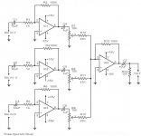
The schematic is for unbalanced lines. Most microphones are balanced.
Have a look here for ideas; balanced/unbalanced preamplifier schematic - Google Search
Have a look here for ideas; balanced/unbalanced preamplifier schematic - Google Search
As I want equiliser support in my mixer, I am simulating an impedance gyrator circuit that is supposed to behave like an inductance. What I am getting is a only a resistive response: both voltage and current are in phase.
Finally, the gyrator circuit behaves like an inductor.
The gyrator circuits I google searched were all vandalised. This continues to strengthen my belief, that to properly learn electronics, the internet has too much vandalism to be a reliable source of information. This is especially true for students.
I remember, about a decade ago, a university student told me that her lecturers penalise anyone quoting wikipeadia for the fact it is unreliable.
The attached circuit is a working gyrator circuit to emulate an inductance.
Attachments
What do you mean by "vandalized"?
In any case, reading random pages here and there is not going to teach Electronics or Audio.
At least, get and download or buy some book(s) professionally written, which follow a logical step by step path, from Basics to whatever you need.
No need to swamp you with Math, but you´ll need some.
In any case, reading random pages here and there is not going to teach Electronics or Audio.
At least, get and download or buy some book(s) professionally written, which follow a logical step by step path, from Basics to whatever you need.
No need to swamp you with Math, but you´ll need some.
I'm not so sure the simulation is working at all tbh. The biasing looks wrong on the opamp (single rail) and the cap is effectively working into the low impedance of the supply.
Snip the opamp out and link the 20k out and you get the same result.
Try this:
Snip the opamp out and link the 20k out and you get the same result.
Try this:
Attachments
Limiting my google search to only .edu sites, it seems, I found a gyrator that emulates an inductor. The schematic is attached and, if my memory servers me right, the voltage leads the current by 90 degrees. Aging is making easy concepts like 'leading' and 'lagging' difficult to imagine concretely. I assume, if the voltage peak is reached 90 degrees before the current peak, it means, the voltage is leading the current.
Please, excuse me for my rusty logic.
Please, excuse me for my rusty logic.
Attachments
You are probably better off just buying a 3 or 4 channel mixer.
The mixer will work good with a microphone and anything else.
It will also have switchable phantom power if required and headphone output.
Behringer do some good stuff.
Should get one cheap on ebay.
The mixer will work good with a microphone and anything else.
It will also have switchable phantom power if required and headphone output.
Behringer do some good stuff.
Should get one cheap on ebay.
Good mic preamps are hard to make. You need lots of gain, (60db) and low noise input, ( because of the gain ). Plus phantom power.
If you don't trust the internet any more may I suggest "The Art of Electronics" by Horowitz and Hill, in any edition.What do you mean by "vandalized"?
..
At least, get and download or buy some book(s) professionally written, which follow a logical step by step path, from Basics to whatever you need.
If you want to understand the specifics problems of preamps for audio microphones you do need to understand headroom, the effects of clipping and the audiability of various forms of harmonics. I suggest you read Hamm 1973 21(4) "Tubes Versus Transistors-is there an Audible Difference" JAES, which is available in paper (but much more easily accessible on line) for starters.
For instrument amplifiers (particularly guitar), any of the books referenced by Rob Robinette.
p.s. any of my students stupid enough to directly quote from or reference wikipedia, rather than the cited source material, is going to get marked down. Doesn't mean it's not a good place to start on technical materials.
Last edited:
Thanks, Mooly. I am reading the document you linked, and I can say, it is a very interesting reading. Till today, I didn't know there were tunable gyrators, and hence, tunable equilizers.
The author stated clearly that the functioning of gyrators is a difficult concept to grasp and focuses largely on explaining their properties.
The author stated clearly that the functioning of gyrators is a difficult concept to grasp and focuses largely on explaining their properties.
Not sure why are you so focused on gyrators; I´d first study general Electronics starting by how components work, then gain blocks, then equalization in general and finally various ways to achieve it, a few of which will rely on gyrators.
Don´t eat dessert before going through the whole meal first, in due order 😛
Don´t eat dessert before going through the whole meal first, in due order 😛
Since I was a young adolescent, back in 1980, I was already interested in how bipolar transistors work. I remember myself at school during midday breaks reading encyclodpaedia articles about them. At the age of 16, one of my elder sisters bought me the full series of 'Elements of Electronics' by F.A. Wilson, published by Bernard Bapani. The series contained five books which I read.
Later on, at the age of 23, I bought more books about electronics. One of them is, 'Microelectronic Circuits', second edition, by Adel S. Sedra and Kenneth C. Smith.
For my A-levels, I studied Physics, Pure Mathematics and Applied Mathematics (Mechanics). At the end of the course, I obtained grade 'A' in the three of them. I sat for these examinations in June 1986.
Capacitors were covered in Electrostatics, Resistors were covered in both ordinary level Physics and advanced, and inductors in Electromagnetism. Transistors, bipolar, were also covered. In fact, I remember there was a question about why a heatsink is necessary for power transistors.
The hardest thing to account for with real components are their imperfections, or better, deviations from idealised components. There is also the problem of parasitics which introduces invisible current paths that may swamp the intended functionality of an electronic circuit. Other problems are unwanted electromagnetic induction and electromagnetic radiation. If we move on in the frequency range, there is yet another formidable limitation, which is the fact that at high frequencies, an electronic current stops to behave like a current, and starts to behave like a longitudinal wave with complexifying side effects like reflection and refraction. This starts to be experienced when a circuit path is about 10% of the electronic wavelength. Unlike light, an electronic field does not travel through a metallic medium at the same speed for all frequencies. At lower frequencies the speed is lower. For very long transmission lines with harmonics in the lower frequency range, this gives rise to race conditions which result in signal distortion in time.
Cool, excellent books and background.
Don´t know Elements of Electronics specifically but Babani is a very good Publisher so it must be good too.
But sadly knowledge fades unless constantly refreshed, (I should know, I forgot German and Russian for lack of practice, keeping English, French, Italian and Portuguese thanks to constant use) so I suggest you reread them, specifically because they go in due order, consider them a sort of "Studies Plan" , and on the side widen your knowledge following along same level info.
Electronics is so interesting that it´s easy to jump all over the place and lose focus 🙂 so apparently taking "the long path", you´ll actually save time 🙂
I suggest doing hands on experiments tracking the theoretical reading, so, say, build a simple power supply when you study them, a simple 1 transistor preamp when you are into it, and so on, step by step.
Including a protoboarded mixer when you reach Op Amps 😱 , protoboarded tone controls when you reach them, and so on.
Your knowledge will be rock solid and above average.
I remember that text. Still on my shelf. H&H is still my go-to for reminders on standard, useful circuits.Later on, at the age of 23, I bought more books about electronics. One of them is, 'Microelectronic Circuits', second edition, by Adel S. Sedra and Kenneth C. Smith.
Hit that in my final year project. The joys of mosfets near cut-off 😀The hardest thing to account for with real components are their imperfections, or better, deviations from idealised components.
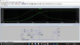
Finally, I succeeded to simulate a gyrator that behaves like an inductor. Connecting this simulated inductor in series with a capacitor produced resonance at 4.7kHz. The circuit is attached.
Ignoring the resistances, the calculated resonance is at 5kHz.
Plotting I(C2) gets a peak at 4.7kHz.
My first, very inexpert impression, is that the current curve may not be adequately selective. If I remember, sharpness of resonance peaks depends on the Q of the inductor.
P.S.
To get a good indication of my retained knowledge of electronics, an online exam would be ideal.
Attachments
I found a site with online exams for electronics. In the following test I got 17/20.
Electronics Test 1 - Online Electronics Test
I also did:
Electronics Test 2 - Online Electronics Test
and got 16/20
I will do more tests.
Electronics Test 1 - Online Electronics Test
I also did:
Electronics Test 2 - Online Electronics Test
and got 16/20
I will do more tests.
Last edited:
- Status
- Not open for further replies.
- Home
- Live Sound
- Instruments and Amps
- Designing and building a mixer circuit.