Hi, so i need a bit of help figuring out what's wrong with these chinese LM3886 PCBs:
So I have 5 of these, and they all present the same problem: As soon as i turn it on, the Zobel resistor gets hot (as in burns if not turned of withing a few seconds).
Things i found out/tried so far:
- Removing the Cap between input and P9 (famous for oscillations) stops the resistor from burning up, however i only have 1-2 seconds of sound then nothing.
- The no sound issue seemed to be due to the chip being muted
- Checking voltages led to realization that somehow the rails go wayyyy off a soon as i turn power on:
-> 35V PSU: Voltage between V+ and GND: starts at 17.8 but quickly moves up to +- 28V! And V- to GND goes down as expected. Which explains why the chip goes to mute.
However i have absolutely no idea why... any ideas?
Attachments


I can't figure out why there's a 2.7Ω + 0.1µF RC series network hanging on the output of the amplifier. Is it there just to annoy the amp? Remove the 2.7Ω + 0.1µF parts and the amp should be fine. It seems like your amp was trying to burn those parts away and heal itself - use a soldering iron to do that and help it out! 🙂
People seem to like to use "Zobels" a lot and they seem to get plastered all over amplifiers without much purpose other than to add more parts to the circuit and maybe if you're unlucky, make it oscillate. There's no need for a "Zobel" to "compensate" for the output series inductor - voltage source amplifiers with loop feedback do not get unstable driving inductors, they get unstable driving capacitors, which is what the silly Zobel looks like. In reality, that's why the inductor was placed in series with the output - to isolate any load capacitance from the amp. Don't undo that with a "Zobel".
You're also right about that 220pF cap from input to pin 9 - delete it. Proper RF filtering would be to place 100pF across the 22kΩ input resistor, but not a cap across the amp inputs. Not sure where this schematic came from, but I'd consult some other designs. Start with the datasheet schematic and see if you need to "improve" it.
For debugging, it makes sense to use an oscilloscope. Your odd voltage readings are what can happen when you have a large RF voltage (from an oscillating circuit) on top of a DC voltage - many voltmeters will read this completely incorrectly, and give you numbers that make no sense. If you see the waveform on a 'scope, it will make much more sense. In general, you don't need a 'scope much faster than 10-20MHz, although 100MHz can be handy for the fastest amplifier chips.
I can't figure out why there's a 2.7Ω + 0.1µF RC series network hanging on the output of the amplifier. Is it there just to annoy the amp?
You may want to refer to the LM3886 data sheet: http://www.ti.com/lit/ds/symlink/lm3886.pdf
And Tom Christiansen has a lot of very good info on implementing these chips. Taming the LM3886 Chip Amplifier
Mike
Can you post a photo with everything connected? It prevents asking a load of stupid questions, like, are you using a heatsink or does the PSU have +0-volts?
One clear problem is the quality of the soldering.
One clear problem is the quality of the soldering.
As I am a complete novice, the first thing I do with my new built amps is check for DC Offset at the output.
My reason for suspecting you may have DC Offset, is that your circuit does not have an output coupling capacitor. Easy enough to measure! You should only have millivolts. I think I have heard on this forum that up to 100mV is acceptable but defer to the experts in all respects.
If there is any DC at pin 3, then there is a risk of speaker damage as I'm sure you are aware!
You may want to refer to the LM3886 data sheet: http://www.ti.com/lit/ds/symlink/lm3886.pdf
And Tom Christiansen has a lot of very good info on implementing these chips. Taming the LM3886 Chip Amplifier
Mike
Thanks for the details! Tom has definitely done a bunch of work with these amplifiers. From these results, it seems that the Zobel helps to increase the phase margin of the amplifier for shunt loads of 0.1µF or greater, but that seems to be pretty far outside of the normal realm of reality.
How much cable has to be used to result in 100nF of bulk capacitance output load? Most small signal cable, even shielded star quad, is at most 50-60pF per foot, so that's 1600 feet of cable before the Zobel does anything that anyone needs to care about. Unshielded speaker cable is going to exhibit much less capacitance per foot, so the numbers should be expanded accordingly.
My concern is that the components installed in these Chinese amplifier boards are not genuine or valid or the right values, and that these possibly bogus Zobel components are directly causing this amplifier to become unstable, while the benefits of this "extended capacitive load compensation" are useless, since the thing catches fire by itself with no load attached.
The safe approach is that if you're not trying to drive 1/5 of a mile of cable, you can delete the probably faulty and incorrectly stuffed Zobel components and enjoy a perfectly functional amplifier.
Pssssttt!!! maybe it´s a CONSPIRACY!!!!! 🙄I can't figure out why there's a 2.7Ω + 0.1µF RC series network hanging on the output of the amplifier. Is it there just to annoy the amp?
People seem to like to use "Zobels" a lot and they seem to get plastered all over amplifiers without much purpose other than to add more parts to the circuit and maybe if you're unlucky, make it oscillate.
Thanks for the details! Tom has definitely done a bunch of work with these amplifiers. From these results, it seems that the Zobel helps to increase the phase margin of the amplifier for shunt loads of 0.1µF or greater, but that seems to be pretty far outside of the normal realm of reality.
Whether the zobel is required or not, the fact that it burns indicates oscillations. Just removing the zobel doesn't fix that and could increase the instability.
I would be very careful to indiscriminately removing or changing comp caps without knowing what you are doing.
There seems to be something wrong with the power supply. Check without a speaker load, are the supplies OK?
Jan
So far thank you all for the input!
Further testing results:
-> The burning Zobel seems to be more of a symptom then the cause of this.
Removing it did not change much. Still 1 or 2 seconds of music and then the odd rhythmic cracking sound which is suspect is a very short moment of "un-mute".
-> Testing the system with no speakers connected (btw. 4 Ohm), showed an output voltage difference of roughly 600mV. Far more interesting though: The supply voltage difference still persist however far less. (+19.7/-15.3)
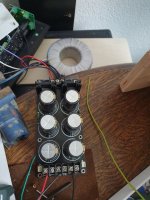
And to answer the basics, yes i am using a +/0/- supply, otherwise i could deliver such readings 😉 and yes i also have a heatsink attached (LM3386TF no V- issue). The one in the picture was just as an example. All the parts are actually just on my lab-bench as i removed them from the intended housing for testing.
Further testing results:
-> The burning Zobel seems to be more of a symptom then the cause of this.
Removing it did not change much. Still 1 or 2 seconds of music and then the odd rhythmic cracking sound which is suspect is a very short moment of "un-mute".
-> Testing the system with no speakers connected (btw. 4 Ohm), showed an output voltage difference of roughly 600mV. Far more interesting though: The supply voltage difference still persist however far less. (+19.7/-15.3)
And to answer the basics, yes i am using a +/0/- supply, otherwise i could deliver such readings 😉 and yes i also have a heatsink attached (LM3386TF no V- issue). The one in the picture was just as an example. All the parts are actually just on my lab-bench as i removed them from the intended housing for testing.
Attachments
PSU input is red, black and black. Where do they come from? What make/model and do you have a schematic of the transformer?
PSU input is red, black and black. Where do they come from? What make/model and do you have a schematic of the transformer?
The middle black one goes to Ground/Earth, i had just had no other color at hand.
The thing is i don't believe it has anything to with the power supply. That one worked fine before, but more importantly, I am seeing the same phenomenon with other PSUs/ Lab PSU.
When no ground, Voltages start at 17.5/-17.5 as expected, then quickly start changing and stabilize at 32.3/-2.7.
I really don't get it... There is always this offset, which just seems to vary depending on the amount of caps/earth connected
Did you try to further decouple it by adding ceramic .1uF caps straight under the board, from each +/-V pin to *nearest* ground (at the IC solder pad?)
Just as a test, using the shortest path physically possible.
In any case, are you scoping output?
Any oscillation? (continuous or short bursts).
Sometimes very high frequency oscillations appear as "grass" ... apparently "way too much white noise".
In that case you are not seeing the oscillation itself but its artifacts.
Hypothesis B: maybe you don´t have "fake/bad ICs" but a plain poorly designed PCB ... or poor build/grounding layout 🙁
The ground wire isn't connected properly.When no ground, Voltages start at 17.5/-17.5 as expected, then quickly start changing and stabilize at 32.3/-2.7.
I really don't get it... There is always this offset, which just seems to vary depending on the amount of caps/earth connected
What you're describing can only happen if "ground" on the amplifier PCB is falling by 14.8 volts with respect to "ground" on the power supply itself, giving the appearance of raising the positive rail voltage, and reducing the negative rail voltage.
This is impossible if there is a ground wire connected - you cannot have 14.8 volts between the two ends of a few inches of wire.
Ergo, the only remaining conclusion is that your ground wire is not connected at both ends, or is high resistance, or the wire itself is internally damaged (unlikely, but possible).
With the power supply off, use an ohmmeter to measure between PCB ground and power supply ground. Also compare your grounding with what the schematic shows. Hopefully that will quickly reveal the missing or bad connection.
With a bad ground, yes, the chip will burst into high frequency oscillation. That's why it smoked your Zobel resistor. A symptom, not a fault.
A good PCB design will have separate traces, maybe separate wires, for small-signal ground, and loudspeaker ground. Make sure to check if your PCB is missing either ground.
-Gnobuddy
Last edited:
The middle black one goes to Ground/Earth, i had just had no other color at hand.
The thing is i don't believe it has anything to with the power supply. That one worked fine before, but more importantly, I am seeing the same phenomenon with other PSUs/ Lab PSU.
When no ground, Voltages start at 17.5/-17.5 as expected, then quickly start changing and stabilize at 32.3/-2.7.
I really don't get it... There is always this offset, which just seems to vary depending on the amount of caps/earth connected
The middle black wire needs to connect to the centre tap of the transformer!
Attachments

That would do it! (See my post just above, #13)The middle black wire needs to connect to the centre tap of the transformer!
-Gnobuddy
The middle black wire needs to connect to the centre tap of the transformer!
Well spotted.
The ground wire isn't connected properly.
What you're describing can only happen if "ground" on the amplifier PCB is falling by 14.8 volts with respect to "ground" on the power supply itself, giving the appearance of raising the positive rail voltage, and reducing the negative rail voltage.
This is impossible if there is a ground wire connected - you cannot have 14.8 volts between the two ends of a few inches of wire.
Ergo, the only remaining conclusion is that your ground wire is not connected at both ends, or is high resistance, or the wire itself is internally damaged (unlikely, but possible).
With the power supply off, use an ohmmeter to measure between PCB ground and power supply ground. Also compare your grounding with what the schematic shows. Hopefully that will quickly reveal the missing or bad connection.
With a bad ground, yes, the chip will burst into high frequency oscillation. That's why it smoked your Zobel resistor. A symptom, not a fault.
A good PCB design will have separate traces, maybe separate wires, for small-signal ground, and loudspeaker ground. Make sure to check if your PCB is missing either ground.
-Gnobuddy
And you were absolutely right!
I actually had 2 issues: one LM3886 (non insulated) somehow hat ground contact... which is why i removed the whole thing from the intended housing for testing purposes, and somehow screwed up the PSU grounding... and somehow also did't re-check it because it worked fine in the enclosure...
But i learned a lot through this 🙂 Thank you all!
I'm glad you were able to find and fix them! 🙂...had 2 issues...
-Gnobuddy
- Status
- Not open for further replies.
- Home
- Amplifiers
- Chip Amps
- Burning chinese LM3386