I'm a longtime lurker, and diyAudio has been invaluable in my tube hifi education. I read the forums extensively to research concepts and projects, and I think I finally came up with a question (hopefully) worthy of a first post. Thank you to all the contributors who've made diyAudio such an amazing resource and community!
I'm currently designing a transformer coupled PP 300B amp inspired by Lynn Olson's work, and am interested in optimizing the phase splitting and volume control at the input. The amp will be driven by a close variation of the EC8010 u-follower RIAA pre-amp in Morgan Jones v4.
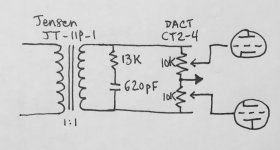
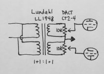
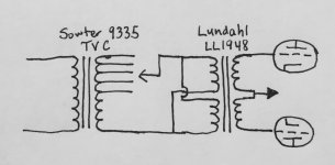
I'm considering the four included schematics. Given a ~200 Ohm source output resistance, are there any significant advantages/disadvantages to these designs?
My instinct says that the Sowter TVC connected to the Lundahl 1+1:1+1 transformer will offer the most balanced attenuation and perfect phase splitting, but perhaps connecting the two transformers will lead to some tricky resonance issues?
Is there any advantage to phase splitting via a 1+1 CT secondary versus via precision matched resistors (or a precision resistive stepped attenuator) as in the other schematics?
Many thanks for your thoughts!
I'm currently designing a transformer coupled PP 300B amp inspired by Lynn Olson's work, and am interested in optimizing the phase splitting and volume control at the input. The amp will be driven by a close variation of the EC8010 u-follower RIAA pre-amp in Morgan Jones v4.
I'm considering the four included schematics. Given a ~200 Ohm source output resistance, are there any significant advantages/disadvantages to these designs?
My instinct says that the Sowter TVC connected to the Lundahl 1+1:1+1 transformer will offer the most balanced attenuation and perfect phase splitting, but perhaps connecting the two transformers will lead to some tricky resonance issues?
Is there any advantage to phase splitting via a 1+1 CT secondary versus via precision matched resistors (or a precision resistive stepped attenuator) as in the other schematics?
Many thanks for your thoughts!
Attachments
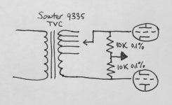
The Sowter alone is not a phase splitter. It's the connection for balanced input to balanced output.
The most convenient solution depends on the rest of the amplifier. It might be a separate SE preamp using the Swoter at the input and driving a input phase splitting transformer in the power amp or it could be again Sowter > SE first stage driving a phase splitting interstage. Two cascaded transformers I am not sure is a good solution as there will be at least one more interstage and the output transformer. Likely two interstages + OT. A bit too many for my taste.
The most convenient solution depends on the rest of the amplifier. It might be a separate SE preamp using the Swoter at the input and driving a input phase splitting transformer in the power amp or it could be again Sowter > SE first stage driving a phase splitting interstage. Two cascaded transformers I am not sure is a good solution as there will be at least one more interstage and the output transformer. Likely two interstages + OT. A bit too many for my taste.
I have been there a number of times. The solutions that work best for me are:
1) Solid state class A preamp that can drive 600R properly + 600R:10KCT input transformer> 1st stage with DHT's > PP bifilar interstage > DHT's driver > bifilar interstage > 300B
2) Same as above but 1st stage DC coupled or RC coupled to the driver
3) Normal preamp driving a 10K:10K+10K input and the rest like 1) or 2)
4) Sowter volume control > SE first voltage gain > concertina splitter> driver > bifilar interstage > 300B.
Option n.4 is the one with a lot less troubles and properly done works very well.
The Sowter TVC although has not got the insulation of a bridging transformer is certainly a lot better than DC or RC coupling. A series of the TVC with a bridging transformer is only recommendable where there is a long cable from the source but of course this cannot be ideal. With too many transformers in the chain frequency response (and also balance at higher frequencies) might be seriously compromised (that's why the choice of the bifilar interstage that properly done can have a huge bandwidth with zero impact on the overall FR and balance). A concertina splitter that has not got heavy duty might be just a good as top quality transformer splitter..if not better!

Lynn's amplifier is unbalanced at the input. Why not build it as given and put the volume control on the output of your preamp?
Attached is a more complete idea of what I have in mind for the amplifier. The source is a phono preamp ~200 Ohm output impedance, ~2Vrms (no room to add a volume control to the phono preamp)
Design goals are:
1) 30-40W output and reasonably low output impedance to allow sufficient power and damping factor to drive conventional loudspeakers of ~87dB sensitivity
2) Minimize output impedance and maximize current of each stage to better drive the Miller capacitance of the proceeding stage and minimize high frequency slew, thereby maximizing high frequency response and phase fidelity.
3) High 6-12dB headroom in the input and driver stages
4) Take advantage of DHT linearity for a no feedback design with higher order harmonics as low as possible
Some concerns I have with the attached schematic:
1) There are a few mentions on diyAudio that when paralleling tubes, each should have its own cathode resistor and bypass cap. Am I implementing this correctly, or might I be better served by a single shared cathode resistor and bypass cap?
2) Transformer coupling each stage: I specified high quality TVC and interstages with bifilar winding, extended LF/HF response, and minimal phase shift. I suppose I could RC or DC couple the mu-follower to a concertina phase splitter and then RC couple to the 45 grids, but am I likely to gain or lose much versus using a very high quality IT?
3) The 6SN7 input has about twice the gain I need assuming a 2Vrms signal. Substituting a 4P1L as the lower tube in the mu-follower will give half the gain, more headroom, greater current to minimize high frequency slew in charging the IT and driver grids, and allow for potentially better DH linearity. I could substitute the Sowter 9395 TVC which has 0/+6/+12dB primary taps to allow for a gain boost if I want to play quieter cut vinyl very loud.
I recognize this is an ambitious and expensive build, so I greatly appreciate your expertise!
Attachments

I use MM transformers extensively, and like them.
5K plate to plate seems high for a PP quartet of 300B, I'd go with something like 1.5K - 2.5K plate to plate.
I would also consider fixed bias.
I got >30Wrms out of a pair in PP into 3.8K @ 2% thd, and 25W @ 1%. (You may be able to find my original article in VTV.)
5K plate to plate seems high for a PP quartet of 300B, I'd go with something like 1.5K - 2.5K plate to plate.
I would also consider fixed bias.
I got >30Wrms out of a pair in PP into 3.8K @ 2% thd, and 25W @ 1%. (You may be able to find my original article in VTV.)
That is one seriously daring plan you are striving for. You are correct, it won't be cheap. But best of luck to you.
My experience has been that the SN7 is one of the world's most linear triodes, but does not enjoy transformer load and the additional capacitive grid load. It exhibits much more linear performance cap-coupled to the next stage instead. Tried Lundahl, MM, Onetics, all with same generalized results; you can do better.
Running the PP45 stage into the 300B stage by means of the MM IT is excellent, difficult to do better there, specifically because of the likelihood of grid current. You won't be disappointed in that.
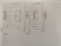
I have attached another possible solution that I used with good success. In particular, I like the use of the Cinemag input transformer that does perform the phase splitting duty if needed. If you have a balanced source, all it then does is provide a highly balanced impedance (key to a balanced topology) at a high value, easy burden for the preamp.
My experience has been that the SN7 is one of the world's most linear triodes, but does not enjoy transformer load and the additional capacitive grid load. It exhibits much more linear performance cap-coupled to the next stage instead. Tried Lundahl, MM, Onetics, all with same generalized results; you can do better.
Running the PP45 stage into the 300B stage by means of the MM IT is excellent, difficult to do better there, specifically because of the likelihood of grid current. You won't be disappointed in that.
I have attached another possible solution that I used with good success. In particular, I like the use of the Cinemag input transformer that does perform the phase splitting duty if needed. If you have a balanced source, all it then does is provide a highly balanced impedance (key to a balanced topology) at a high value, easy burden for the preamp.
Attachments
What a beautiful and ambitious project! Personally, I wouldn't change the output loading at all; it's perhaps the most luxury part of the circuit - but that's just me.
If you're looking for potential refinements I'd only recommend Zobels be included for the secondaries of the interstage transformers. If the manufacturer can't provide recommended values, they're not serious people. There's not a lot to be done about the series resonance of the 2uF capacitor and the first interstage transformer's primary inductance, but it needs to be well outside any possible signal. Not fatal, just best practice.
And you definitely want a grid stop resistor at the first stage and probably a grid pull-down resistor, "just 'cause".
All good fortune with your beautiful project,
Chris
In addition to others' comments...
The other solution (which I prefer) is getting a "better" 300B more suited for high power PP. This is the EML 300XLS or 320B XLS. They do not cost a lot more than the standard EML, actually a pair of these will cost less than a quad of the standard type (and about the same as a quad of less fancy 300B of good quality) but the 320B (rated 65W) especially can work at 45W plate dissipation and last at least as a standard 300B working at 28-30W plate dissipation. KR also makes the 300B XLS and is actually rated even more at 70W with max 600V plate voltage!
All these 300B variants basically have a more powerful filament running at 1.5-1.8A depending on the model and improved cooling. Otherwise they are 300B's in every aspect.
Unfortunately the 4P1L is too microphonic at lowish signal level. Unless you can tame it I would discard this. If you can manage microphonics you could also consider a true triode like the 26. If you use a linear device there is no need of a mu-follower.
That is a bit overdoing things. 3 dB is already plenty considering the amp is 30-40W, IMHO.3) High 6-12dB headroom in the input and driver stages
If the output transformer can withstand some DC unbalance you can try with a common resistor for each PP pair. Linear devices are more flexible in this respect.Some concerns I have with the attached schematic:
1) There are a few mentions on diyAudio that when paralleling tubes, each should have its own cathode resistor and bypass cap. Am I implementing this correctly, or might I be better served by a single shared cathode resistor and bypass cap?
The other solution (which I prefer) is getting a "better" 300B more suited for high power PP. This is the EML 300XLS or 320B XLS. They do not cost a lot more than the standard EML, actually a pair of these will cost less than a quad of the standard type (and about the same as a quad of less fancy 300B of good quality) but the 320B (rated 65W) especially can work at 45W plate dissipation and last at least as a standard 300B working at 28-30W plate dissipation. KR also makes the 300B XLS and is actually rated even more at 70W with max 600V plate voltage!
All these 300B variants basically have a more powerful filament running at 1.5-1.8A depending on the model and improved cooling. Otherwise they are 300B's in every aspect.
Surely there is something you cannot do in your schematics. This is using the IT-02 as phase splitter. Bifilar IT's can only be SE:SE or PP😛P otherwise they will not be balanced at higher frequency. You need to use a transformer made for splitting and the best performers are usually small input transformers that cannot take any DC imbalance being made of low loss high permeability materials. If interstage then the Hashimoto 105K or 107K are very good choices anyway if you are not after 100 KHz bandwidth. That's why I suggest the concertina phase splitter as an option to take into serious consideration (you can also think about an LTP if like). It always depends on how it's done and the task it has. It can be bad, average or superlative....2) Transformer coupling each stage: I specified high quality TVC and interstages with bifilar winding, extended LF/HF response, and minimal phase shift. I suppose I could RC or DC couple the mu-follower to a concertina phase splitter and then RC couple to the 45 grids, but am I likely to gain or lose much versus using a very high quality IT?
3) The 6SN7 input has about twice the gain I need assuming a 2Vrms signal. Substituting a 4P1L as the lower tube in the mu-follower will give half the gain, more headroom, greater current to minimize high frequency slew in charging the IT and driver grids, and allow for potentially better DH linearity. I could substitute the Sowter 9395 TVC which has 0/+6/+12dB primary taps to allow for a gain boost if I want to play quieter cut vinyl very loud.
I recognize this is an ambitious and expensive build, so I greatly appreciate your expertise!
Unfortunately the 4P1L is too microphonic at lowish signal level. Unless you can tame it I would discard this. If you can manage microphonics you could also consider a true triode like the 26. If you use a linear device there is no need of a mu-follower.
Last edited:
Surely there is something you cannot do in your schematics. This is using the IT-02 as phase splitter. Bifilar IT's can only be SE:SE or PP😛P otherwise they will not be balanced at higher frequency. You need to use a transformer made for splitting and the best performers are usually small input transformers that cannot take any DC imbalance being made of low loss high permeability materials. If interstage then the Hashimoto 105K or 107K are very good choices anyway if you are not after 100 KHz bandwidth. That's why I suggest the concertina phase splitter as an option to take into serious consideration (you can also think about an LTP if like). It always depends on how it's done and the task it has. It can be bad, average or superlative....
Understood regarding avoiding bifilar IT for phase splitting SE😛P. I'll rework the schematic to reflect this. Thank you!
I'm still confused whether the Sowter TVC (mu-metal core, +20dBU @ 20Hz max input) could be wired to phase split an unbalanced input, per my attached example.
Jensen describes a similar idea with the JT-11P-1 line input transformer: https://www.jensen-transformers.com/wp-content/uploads/2014/08/as060.pdf
Can the above implementation match a dedicated 1+1:1+1 line input transformer designed for phase splitting? Can it match or exceed the performance of a concertina?
Attachments

You can ask them directly. The balanced output can only be if the input is balanced from their application sheet. You can have an unbalanced output from balanced input. Transformers of different brands might have different geometry hence different distributed capacitance so in principle they are not equivalent by default.I'm still confused whether the Sowter TVC (mu-metal core, +20dBU @ 20Hz max input) could be wired to phase split an unbalanced input, per my attached example.
Can the above implementation match a dedicated 1+1:1+1 line input transformer designed for phase splitting? Can it match or exceed the performance of a concertina?
I've spoken with Sowter and wanted to give an update.
The transformer attenuators (9335/9395) are "bifilar wound with a high interwinding capacitance" and will thus not work well for unbalanced -> balanced because the signal to the grids will not stay balanced at high frequencies.
The Sowter 3575 and 1475 on the other hand work for unbalanced in to balanced out.
I have attached another possible solution that I used with good success. In particular, I like the use of the Cinemag input transformer that does perform the phase splitting duty if needed. If you have a balanced source, all it then does is provide a highly balanced impedance (key to a balanced topology) at a high value, easy burden for the preamp.
>> Hi Could you use the Cimemag ( secondary ) to phase split 6N1P drivers for EL84 PP ?
Sure, it is an excellent splitter. To clarify, you will want to split prior to the 6N1P stage, not after. That xfmr will not like heavy loads, resistive or reactive, especially when being expected to maintain phase/mag balance between the two sides. It also wants zero DC current. Not suitable for interstage transformer duty - it is truly an input transformer.
Seems this Jensen JT-11SS-DLCF-1:2 https://www.jensen-transformers.com/wp-content/uploads/2014/11/jt-11ss-dlcf-12.pdf
could be configured for tube SE>PP as a phase splitter as long as you lifted the DC of the input
could be configured for tube SE>PP as a phase splitter as long as you lifted the DC of the input
- Status
- Not open for further replies.
- Home
- Amplifiers
- Tubes / Valves
- Optimizing Input Transformer Phase Splitting and Volume Control