The production F5 used a 300VA 2x18VAC Plitron, so that gives some guidance.
My FW clone builds used 300VA and 400VA Anteks (both shielded and
unshielded) and regular 300VA Plitrons. All have been quiet.
Cheers,
Dennis
My FW clone builds used 300VA and 400VA Anteks (both shielded and
unshielded) and regular 300VA Plitrons. All have been quiet.
Cheers,
Dennis
I successfully fried one channel of my amp !
Series of events:
1. Amplifier had been left on for a few days.
2. Turns on preamp
3. Heard a quite pop in speakers and no noise from source when turned it on.
4. Pull out amp, checked the fuse, fuse was blown.
5. Replaced fuse, turned amp back on and it went BZZZZZZZZZ, sparked a bit inside at the terminal strip, at the live in and CL-60, then blew the fuse.
6. Said Oh Sh@@@@
7. Plugged in bulb limiter, replaced fuse and the bulb lit up like it was gonna explode
8. Unplugged left and right channel from PSU, tested PSU - good
9. Tested right channel fine, no short and audio worked.
10. Tested left channel - build lights up hot so there is something wrong
11. Look at left channel and it's FRIED.
Here is a picture.
Not sure what happened but the good news is that DIY store has all the parts I need.
I have some Toshiba FETS and my one working channel are from LS so it's probably best to redo both channels so they are all matched?
Attachments
bias? ambient temp? cl60? dry joint? failed component? or maybe cat was lying on left heatsink? i dont see how there would be sparks at mains in cl60 terminals other than bad connection there? please correct me if i'm wrong.
brian.
brian.
It is the Nutube B1 preamp and it doesn't have a thump. I did test the preamp on a two other amps afterwards and no pop or thump but it could have been from it.
I'd been using the amp for months with no issues, preamp for a few weeks no issues. Biased corrrectly, temps, offset should have all been fine as I checked it about a month ago.
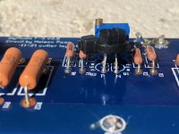
Here is a picture of where it sparked.
Now I pulled the wires out and I originally soldered the Live In to the CL-60 leg for some reason then screwed it down into the terminal where i drew a circle. Maybe that had something to do with it because it wasn't a super pretty joint but was strong. Maybe it just didn't have good contact with the strip, the wire in and the CL60 leg.
I'd been using the amp for months with no issues, preamp for a few weeks no issues. Biased corrrectly, temps, offset should have all been fine as I checked it about a month ago.
Here is a picture of where it sparked.
Now I pulled the wires out and I originally soldered the Live In to the CL-60 leg for some reason then screwed it down into the terminal where i drew a circle. Maybe that had something to do with it because it wasn't a super pretty joint but was strong. Maybe it just didn't have good contact with the strip, the wire in and the CL60 leg.
Attachments

My other mistake was I should have plugged in the bulb limiter after the fuse blew the first time.
board distorted by heat so R14 touches heatsink? i doubt on grounds of the obvious.
Last edited:
I'm finally getting around to fixing my F5. It's one of those things where I wasn't too mad something went wrong because now I get to build a new one 🙂
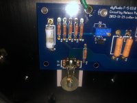
One board is just fine so the JFETs I know are ok. Should I assume the JFETs on the fried board are no good?
Visually they look good while other components are clearly fried. I already acquired replacement JFETs but it would be nice to save these if they are still good.
Here is a pic
One board is just fine so the JFETs I know are ok. Should I assume the JFETs on the fried board are no good?
Visually they look good while other components are clearly fried. I already acquired replacement JFETs but it would be nice to save these if they are still good.
Here is a pic
Attachments
I successfully fried one channel of my amp !
Series of events:
1. Amplifier had been left on for a few days.
2. Turns on preamp
3. Heard a quite pop in speakers and no noise from source when turned it on.
4. Pull out amp, checked the fuse, fuse was blown.
5. Replaced fuse, turned amp back on and it went BZZZZZZZZZ, sparked a bit inside at the terminal strip, at the live in and CL-60, then blew the fuse.
6. Said Oh Sh@@@@
7. Plugged in bulb limiter, replaced fuse and the bulb lit up like it was gonna explode
8. Unplugged left and right channel from PSU, tested PSU - good
9. Tested right channel fine, no short and audio worked.
10. Tested left channel - build lights up hot so there is something wrong
11. Look at left channel and it's FRIED.
Here is a picture.
Not sure what happened but the good news is that DIY store has all the parts I need.
I have some Toshiba FETS and my one working channel are from LS so it's probably best to redo both channels so they are all matched?
Your soldering looks pretty rough from what i can see.What kind did you use? I would resolder using flux and 63/37 solder.It may save you a failure down the road.
It is the Nutube B1 preamp and it doesn't have a thump. I did test the preamp on a two other amps afterwards and no pop or thump but it could have been from it.
I'd been using the amp for months with no issues, preamp for a few weeks no issues. Biased corrrectly, temps, offset should have all been fine as I checked it about a month ago.
Here is a picture of where it sparked.
Now I pulled the wires out and I originally soldered the Live In to the CL-60 leg for some reason then screwed it down into the terminal where i drew a circle. Maybe that had something to do with it because it wasn't a super pretty joint but was strong. Maybe it just didn't have good contact with the strip, the wire in and the CL60 leg.
You should never solder a wire then put it under a screw.The solder relaxes after a period of time and you get a loose joint.
^^ A great point. 
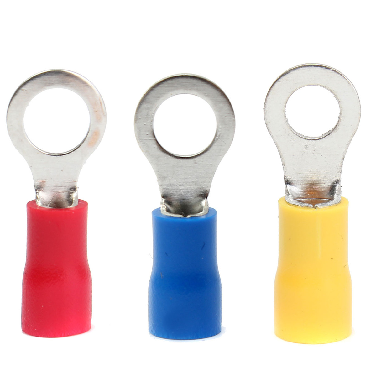
The best solution when using barrier strips like that is ring terminals on all the connections -
The best solution when using barrier strips like that is ring terminals on all the connections -
^^ A great point.
The best solution when using barrier strips like that is ring terminals on all the connections -
Those are what I used on my CL-60's with a barrier strip,worked excellent.
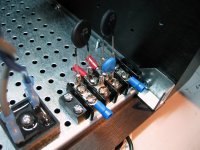
Here is a mockup of a barrier strip I used for one of my amps. I couldn't get a trustworthy airtight crimp on the thin leads, so I soldered the connection after crimping. In subsequent amps I used a different type of connector and also insulating "marking strips" under the barrier strip. I suppose some flame-resistant material on the exposed CL60 leads is also good practice. These critical PS connections need to be high-reliability, which is not something always achieved by screw-down on stranded wire.
BK
BK
Attachments
Here is a mockup of a barrier strip I used for one of my amps. I couldn't get a trustworthy airtight crimp on the thin leads, so I soldered the connection after crimping. In subsequent amps I used a different type of connector and also insulating "marking strips" under the barrier strip. I suppose some flame-resistant material on the exposed CL60 leads is also good practice. These critical PS connections need to be high-reliability, which is not something always achieved by screw-down on stranded wire.
BK
You also need a quality crimping tool, I got intermittent connections using a cheap consumer one. I changed over to soldering wherever possible.
Those are what I used on my CL-60's with a barrier strip,worked excellent.
Do you guys just crush these things on? I cant get comfy with that. I grab the ring with an old pair of large needle nose pliers, stick the plastic end in flame until it begins to catch fire and scrap the plastic off. crush it to wire and solder. Then cover with heat shrink.
Russellc
Cody,
Get a real crimper, you'll understand. They are actually fantastic connections.
https://www.amazon.com/dp/B07H94F5X3/ref=cm_sw_em_r_mt_dp_U_4-nOCbAEZKNNT
Get a real crimper, you'll understand. They are actually fantastic connections.
https://www.amazon.com/dp/B07H94F5X3/ref=cm_sw_em_r_mt_dp_U_4-nOCbAEZKNNT
- Home
- Amplifiers
- Pass Labs
- An illustrated guide to building an F5