This is indeed ana interesting topic. I have to confess that I really thought I had a correct idea of what is going on in PCM and OS. After reading this thread I'm not so sure anymore.
And I don't think anyone has yet made that super clear, explain to my mother, kind of description on how it really works.
Pictures would help I suppose. Using 44,1 and picturing as a start something like...
//
I don't believe that DSP science much lends itself to simple explanations that your mother would understand. Much of it is non-intuitive.
As I mentioned upthread, interpolative oversampling is, essentially, an signal reconstruction technique. I feel that the process of signal reconstruction is most easily understood in the fequency-domain. For illustration, in that unreconstructed signal spectrum chart you attached, the left-most green block is the desired signal band, also known as, the baseband. To fully recover/reconstruct the original baseband signal, essentially, what needs to be done is to remove all bands to the right of the baseband, which are the repeating image bands.
The frequency-domain shows that signal reconstruction is an low-pass filtering process, where as the time-domain shows that signal reconstruction is an interpolation process. They are two-sides of the same coin, as it were, depending on whether the signal is viewed in the time-domain, or in the frequency domain. In the frequency-domain, we see that it is low-pass filtering taking place. In the time-domain, we see that it is also interpolation taking place. Either way, they are fundamentally the same digital process.
Interpolate an oversampled signal in the time-domain and it is inherently low-pass filtered in the frequency-domain. Low-pass filter an oversampled signal in the frequency-domain and it is inherently interpolated in the time-domain. This shows why you cannot fully separate oversampled interpolation from digital filtering. They are simply different ways of viewing the reconstruction process. Up/Oversampling the data conversion rate is necessary so as to open up spectrum in which to relocate the filtered image bands, as digital filters don't so much remove the images as they relocate them higher in frequency, but only if spectrum is made available.
<snip>
And I don't think anyone has yet made that super clear, explain to my mother, kind of description on how it really works.
Pictures would help I suppose. Using 44,1 and picturing as a start something like...
//
The topic resp. the implication are often a bit counterintuitive.
Given the redundance in the frequent posts trying to explain what is happening during "upsampling/oversampling" i have to agree that we failed up to a certain degree.
Pictures would obviously help ......
I don't believe that DSP science much lends itself to simple explanations that your mother would understand. Much of it is non-intuitive.
True, a basic understanding of time vs. frequency domain, FFT's, and convolution would help the most. I don't think the down and dirty of DSP programming is necessary.
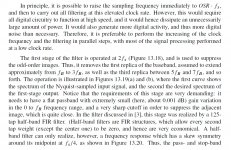
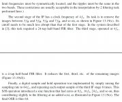
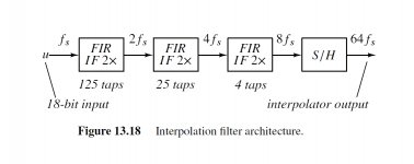
Ken and Scott, if you think all the interpolation points are equally important, it's not correct. The reason why I have been advocating Audirvana upsampling + high quality FIR pre-filter is, 2*fs points are far more critical than higher fs interpolation points, and just to determine 2*fs points while avoiding audio band ripple requires so much processing power that can’t be handled by current DAC chips. (I’m talking about 44.1K source). Plotting better 2*fs interpolation point can greatly improve audio band transient response of the regular oversampling DAC. It is the same reason why Chord is offering high quality interpolation filter before DAC, and I don’t think Chord is calculating all those 8x interpolation points equally, because it’s hard to believe it can be done with their limited FPGA’s processing power, and it's nonsense to calculate higher fs points as accurately as lower points.
Last edited:
Plasnu, as for me, I've no idea what you are asserting. So, I'll make no attempt to address it.
Plasnu, as for me, I've no idea what you are asserting. So, I'll make no attempt to address it.
How do you think the interpolation points are determined? It's not a simple process like just adding zero at upsampling process, which you call pseudo-upsampling.
Last edited:
What Plasnu is referring to sounds like it has to do with particulars of how interpolation filtering is best implemented. If we need to upsample by Nx, rather than doing Nx all at once, for example, it can be better to do 2x then another 2x then the last 2x, etc. In that case, the first 2x takes most of the processing resources. (The above assumes N is non-prime.)
The ideas are explained in the book, Understanding Delta-Sigma Data Converters. Some attachments below illustrate.
The ideas are explained in the book, Understanding Delta-Sigma Data Converters. Some attachments below illustrate.
Attachments
Last edited:
How do you think the interpolation points are determined? It's not a simple process like just adding zero at upsampling process, which you call pseudo-upsampling.
The interpolated samples are computed by the filter to be as those values which low-pass filter away the image bands. There is no guessing or estimating involved, within the precision limits of a given filter implementation. So, I've been suggesting that interpolation is easier to understand if viewed in the frequency-domain, where it transforms in to low-pass filtering operation, rather than in the time-domain, where it wrongly tends to be viewed as an estimating of missing 'in between' sample values only implied by the available sample values.
What Plasnu is referring to sounds like it has to do with particulars of how interpolation filtering is best implemented. If we need to upsample by Nx, rather than doing Nx all at once, for example, it can be better to do 2x then another 2x then the last 2x, etc. In that case, the first 2x takes most of the processing resources. (The above assumes N is non-prime.).
Hi, Markw4, yes but that has to do with processing resource conservation, not filter accuracy, precision, or artifact minimization. It is an hardware conservation stratgy most commonly seen in on-chip based digital filters.
Ken and Scott, if you think all the interpolation points are equally important, it's not correct.
I understand what you are saying but I'm not sure of the relative differences and how much they would matter. Why not just use SoX to create 2fs files and compare?
There are those that would say if you create a "perfect" 88.2k file why not just use a multi-bit DAC and analog filtering? I'm assuming SoX is doing the 2fs SRC real time. I've never tested SoX for its limits on this.
The interpolated samples are computed by the filter to be as those values which low-pass filter away the image bands. There is no guessing or estimating involved, within the precision limits of a given filter implementation. So, I've been suggesting that interpolation is easier to understand if viewed in the frequency-domain, where it transforms in to low-pass filtering operation, rather than in the time-domain, where it wrongly tends to be viewed as an estimating of missing 'in between' sample values only implied by the available sample values.
It is no estimating/guessing involved but the "in between" samples are indeed reconstructed based on the available original sample values.
In the mathematical sense it is still called "interpolation" although in a perfect world it would be perfect interpolation, a special case of the so-called "Lagrange interpolation" , so the time-domain point of view isn´t wrong as long as one keeps in mind that the "available samples" already contain all the information that is needed to reconstruct everything "in between" .
Although i agree that frequency domain pictures help a lot in understanding, time domain pictures are needed as well to get the meaning of the whole thing.
It is no estimating/guessing involved but the "in between" samples are indeed reconstructed based on the available original sample values.
Yes, of course they are. My point is that interpolated values aren't estimated from the available samples, but are accurately computed from them.
...so the time-domain point of view isn´t wrong as long as one keeps in mind that the "available samples" already contain all the information that is needed to reconstruct everything "in between" .
Agreed, the time-domain view isn't wrong. I'm simply suggesting that it's much less humanly intuitive than the time-domain view. The do represent the same imformation, but in reciprocal forms.
Although i agree that frequency domain pictures help a lot in understanding, time domain pictures are needed as well to get the meaning of the whole thing.
We may not fully agree here. I tend to find that an time-domain view serves to confuse people regarding interpolative reconstruction. Leading them to the common mistaken belief that interpolated values can only be estimated.
Hi, Markw4, yes but that has to do with processing resource conservation, not filter accuracy, precision, or artifact minimization. It is an hardware conservation stratgy most commonly seen in on-chip based digital filters.
True, still sounds a lot like where plasnu seemed to be coming from, at least it did to me.
So, I've been suggesting that interpolation is easier to understand if viewed in the frequency-domain, where it transforms in to low-pass filtering operation, rather than in the time-domain, where it wrongly tends to be viewed as an estimating of missing 'in between' sample values only implied by the available sample values.
I guess everyone uses whatever mental representation works for them. For myself I visualize joining up the samples with fragments of sinewaves which are fully constrained by the frequency domain band-limiting. Just as a straight line interpolation is fully constrained by Euclidean geometry so there can only be one solution to drawing a straight line between two points, so interpolation has its own geometry which fully constrains the waveform between the two sample points.
True, a basic understanding of time vs. frequency domain, FFT's, and convolution would help the most. I don't think the down and dirty of DSP programming is necessary.
The material here The Scientist and Engineer's Guide to Digital Signal Processing might be useful for those looking for an introduction. All of the material from the book may be downloaded for free.
Pictures would help I suppose. Using 44,1 and picturing as a start something like...
//
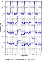
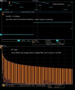
I also like an intuitive explanation rather than the mathematical one. My goal in reconstruction filter is to remove images as possible as I can. Images inevitably created by digital sampling look like stairstep in the time domain. So, if your digital filter can output stairstep-free waveform, your job is successful, intuitively. The 1st pic is 12kHz sinewave sampled by 96kHz(x1OSR), where you have only 8 horizontal resolutions which end up stairstep and probably many remaining images. FFT plot in orange says yes. Hard stairstep is equal to many images. In x1OSR, a digital filter has no power to remove images because their controllable bandwidth is up to Fs/2 while images are above Fs/2(even the 1st is from Fs/2 to 3*Fs/2).
This is a fundamental limitation of a digital filter. If your digital filter is LPF from 0 to 20kHz(precisely speaking, only BPF exists in the digital domain), you can remove images at HF. It's true if your filter is analog. But it's not true if your filter is digital. Why can't LPF remove images at HF??? The answer is simple. A digital filter has multiple passbands while analog one has only one passband. I guess this cause confusion about oversampling. If a digital filter had one passband, you wouldn't need to do oversampling.
The reason why a digital filter has multiple passbands is an inevitable consequence. A transfer function of a digital filter is a series of sin and cos. Sin and cos are a periodic function. So, a digital filter is also a periodic function. In the frequency domain, Fs is equal to 2*pi, where 10kHz and (10kHz+Fs) have the same output,ie sin(x)=sin(x+2*pi). Your LPF from -20kHz to 20kHz always appears from (-20kHz+n*Fs) to (20kHz+n*Fs). This is the cause of multiple passbands. The baseband LPF unconsciously makes multiple passbands which prevent you from removing images because images are also at passband.
The only solution to break the periodicity is to employ high sampling frequency. A digital filter itself has no power. Only high sampling frequency, in other words, high horizontal resolution in the time domain can do the job. Intuitively speaking, only high horizontal resolution can decrease stairstep. You must keep it in mind that a digital filter has multiple passbands because it's a periodic function caused by sin and cos.
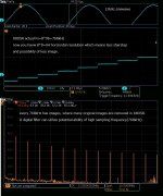
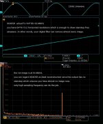
The 2nd pic is x8OSR. No need to explain why it works well. High horizontal resolution(64) guarantees fewer images as you see. The 3rd is x64OSR. You can regard this as an ideal reconstruction because the output has almost stairstep-free. The 1st image at 6144kHz means quasi one passband even if a digital filter is used. This is the destination.
The true meaning of oversampling in reconstruction is to break the inherent nature of periodicity. If your digital filter is for crossover, no need to have an oversampling process since your target is below Fs/2 though it has multiple passbands. Reconstruction process must be under Fs/2. After the proper oversampling process, A digital filter can do the job for reconstruction.
Attachments
Wrt interpolation, there is for example the method, described by Shannon in his famous paper, that delivers a perfect interpolation which means a reconstruction of the original signal. Others are possible.
Unfortunately the conditions needed for perfect sampling and reconstruction can´t be met in the real world.
The zero-order hold (staircase) output is already an interpolation, the first-order hold (piecewise linear line) is another.
Iirc Wadia used in the 80s their so-called "french curve algorithm" based on spline interpolation, i should reread about Bezier curves but think it is special as in contradiction to most other interpolation strategies the resulting continuos line is a smooth one, but does not have the original samples to be part of this curve.
Wadia obviously traded better amplitude linearity and stopband attenuation for better time response (short impulse reaction) with the risk of more IMD if high level content around the upper audio bandwidth limit was sampled.
I´ll try to put some graphs for the time and frequency domain together that might help...
Hi guys
I haven’t read through all the technical discussion in this threat but have two basic question:
1. Is it advisable to use upsampling by software such as Audirvana and output to a NOS DAC at 2x or 4x sample rate? I understand that this would help correct the HF roll off character of NOS DAC?
2. Does the upsampling process suffer from similar issues that are associated with oversampling digital filter on a chip? I mean signal phase and pre, post ringing?
I have heard a many NOS DAC and I can’t hear any artifacts of the images but the treble roll off does happen with music containing top HF.
Why....
Why is this thread so long?
Wikipedia states:
The thread title, "Oversampled DAC without digital filter vs NOS", hence, is nonsensical.
Why is this thread so long?
Wikipedia states:
A digital filter system usually consists of an analog-to-digital converter (ADC) to sample the input signal, followed by a microprocessor and some peripheral components such as memory to store data and filter coefficients etc. Finally a digital-to-analog converter to complete the output stage.
The thread title, "Oversampled DAC without digital filter vs NOS", hence, is nonsensical.
I just luuuuuuuuuuuuuuuuuuuuuuv this word salad....
So do these guys ...Just as a straight line interpolation is fully constrained by Euclidean geometry so there can only be one solution to drawing a straight line between two points, so interpolation has its own geometry which fully constrains the waveform between the two sample points.
Last edited:
- Status
- Not open for further replies.
- Home
- Source & Line
- Digital Line Level
- Oversampled DAC without digital filter vs NOS