Hi all
First post in the Valves section!!
I've just acquired my 3rd set of Quad II amps (sold my chrome ones about 12 years ago for some god only known reason!).
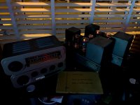
These latest ones are largely original and came with the Quad 22 and FM tuner too.
I've done some basic checks before use including the mains selector which required attention and checking the bias.
I was aware that there had been some preventative maint carried out previously when I picked these up.
When I opened the amps, I found a few resistors changed (no problem).
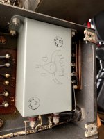
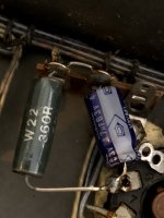
I also see that someone has left a signature on the smoother cap body (C4&6) 😉
Does anyone recognise the trade mark>>>??
I've got Russian PIO to go back in place of the orange caps (C2 & C3).
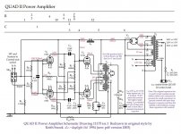
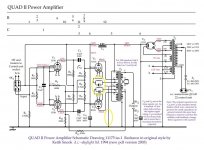
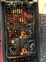
My main question relates to the relocation of the bias resistor and cap.
In the original circuit there is a singe R (known to be underrated) and C which are mounted on the unused choke tags. (I know this also can cause the choke to get warm and leak the tar causing choke issues).
These are after the transformer winding in the path to gnd in the original.
Mine have the R & C moved to Pin 8 on the KT66's directly and now live in front of the transformer winding.
The new values are 360r & 47uF.
My plate voltage is 357v which is a bit high? Think it should be about 330v. Resistor is 360r and I have 26.5v and 27.5v on them. So that’s 72mA and 76mA.
Firstly, I wonder if I change to 420r that brings it back to 62mA and 65mA which I think is closer the intended Bias value???
Also, I think this takes the amp out of Ultra Linear mode? Can someone confirm and also maybe offer any pro's & con's which could lead me to understand why it has been changed.
Few pics attached explaining!
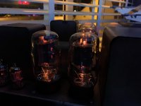
As I say, go gentle with me, I'm very much at home in low voltage stuff but have very limited experience with beautiful big glowy glass things 🙂😉
*circuit taken from Keith Snook website with my edits for changes to the bias.
Thanks 🙂🙂
First post in the Valves section!!
I've just acquired my 3rd set of Quad II amps (sold my chrome ones about 12 years ago for some god only known reason!).
These latest ones are largely original and came with the Quad 22 and FM tuner too.
I've done some basic checks before use including the mains selector which required attention and checking the bias.
I was aware that there had been some preventative maint carried out previously when I picked these up.
When I opened the amps, I found a few resistors changed (no problem).
I also see that someone has left a signature on the smoother cap body (C4&6) 😉
Does anyone recognise the trade mark>>>??
I've got Russian PIO to go back in place of the orange caps (C2 & C3).
My main question relates to the relocation of the bias resistor and cap.
In the original circuit there is a singe R (known to be underrated) and C which are mounted on the unused choke tags. (I know this also can cause the choke to get warm and leak the tar causing choke issues).
These are after the transformer winding in the path to gnd in the original.
Mine have the R & C moved to Pin 8 on the KT66's directly and now live in front of the transformer winding.
The new values are 360r & 47uF.
My plate voltage is 357v which is a bit high? Think it should be about 330v. Resistor is 360r and I have 26.5v and 27.5v on them. So that’s 72mA and 76mA.
Firstly, I wonder if I change to 420r that brings it back to 62mA and 65mA which I think is closer the intended Bias value???
Also, I think this takes the amp out of Ultra Linear mode? Can someone confirm and also maybe offer any pro's & con's which could lead me to understand why it has been changed.
Few pics attached explaining!
As I say, go gentle with me, I'm very much at home in low voltage stuff but have very limited experience with beautiful big glowy glass things 🙂😉
*circuit taken from Keith Snook website with my edits for changes to the bias.
Thanks 🙂🙂
Attachments
UL in Quad II?! Mr. Walker would be turning in his grave...😉 Changing KT66s’ cathode resistors to bring the bias to spec is a good idea though.Also, I think this takes the amp out of Ultra Linear mode?
There's information on the Cathode resistor/cap change on Keith's website here -
~ QUAD II Valve Power Amplifier Modernising and Modifying ~
The relevant part begins with the paragraph, "Because the R12/C5 networks are no longer common to both output valve cathodes they have a greater effect on the low frequency response and are now used to deliberately reduce the LF response of the output stage"
Leave it alone. Somebody has provided individual cathode circuits. That means the resistor is doubled, and the capacitance ditto. Consider that both cathodes are more or less in parallel to ground via these circuits. The HT voltage is OK at anywhere between 330-360V. The KT66s are still loafing. If you have GZ34s change them to GZ32s as designed.
The Quad II is not a UL amplifier, and changing the cathode circuit cannot affect that.
The business of the original resistors being under-rated seems to be urban myth. I've never seen a burnt one. The reality can only be that they dissipate 3.8W just fine, especially when mounted in an airstream as they were. You should make sure yours are mounted well free of the valve sockets and well away from the capacitors.
NB The correct current is given by 26V/180 ohms, which yields 144mA for two valves, or 72mA per valve, with a tolerance of 20%, and you are miles within that.
I'm not convinced about the bypass capacitor values. It seems to me they should have been halved, not doubled.
I believe the bull's-head drawing is by Haden Boardman. Enough said really.
I'm not convinced about the bypass capacitor values. It seems to me they should have been halved, not doubled.
I believe the bull's-head drawing is by Haden Boardman. Enough said really.
Thanks for the reply's guys.
ejp, i see the logic there with the values. Do you not think that >70mA is too high bias as jazbo8 suggests?
6L6, thought I'd read every word on Mr Snooks website (inc the 405 stuff), somehow managed to miss that section (or at least I didnt recall it).
I can see why it would be a good idea to control bias separately, assuming the state of the tube itself well effect the bias current readings.
Re the UL question, I obviously got the wrong end of the stick whilst assimilating info on the www lol
Any clues on the trademark drawn on the cap housing?
thanks 🙂
What I think is that 26/180/2 = 0.072. No further thought is required. I don't see where jazbo8 has said anything different, or anybody else, and if they have, they're wrong, by definition. And Quad stated that the distortion specification holds with valve current mismatches of up to 20%. This allows you anything between ~58mA and ~86mA.
I would personally remove these new cathode circuits and restore the original shared 180R||25uF(50V), making sure to use a 5W resistor, mount it well clear of the choke terminals using the full lead length available, and mount the capacitor over to the right (near the GZ32) against the chassis well away from the resistor.
You need to consider that this design is nearly 75 years old and that thousands of original examples are still going strong with the original valves. I have two right here. You can't argue with that.
I will look up about the cathose bypass capacitor value tonight, but I'm practically certain it's wrong at 47uF per KT66. I note that Keith Snook uses 390R||10uF.
Last edited:
My comments regarding the bias was in response to the following:
Which was not close to the spec of 72mA as you have just shown. I would also encourage the OP to read Patrick Turner's page on Quad-II, as there are good reasons for employing separate cathode networks for the output stage (among other modifications).
Firstly, I wonder if I change to 420r that brings it back to 62mA and 65mA which I think is closer the intended Bias value???
Which was not close to the spec of 72mA as you have just shown. I would also encourage the OP to read Patrick Turner's page on Quad-II, as there are good reasons for employing separate cathode networks for the output stage (among other modifications).
... The new values are 360r & 47uF.
My plate voltage is 357v which is a bit high? Think it should be about 330v. Resistor is 360r and I have 26.5v and 27.5v on them. So that’s 72mA and 76mA.
Firstly, I wonder if I change to 420r that brings it back to 62mA and 65mA which I think is closer the intended Bias value???
Also, I think this takes the amp out of Ultra Linear mode? Can someone confirm and also maybe offer any pro's & con's which could lead me to understand why it has been changed.
First, do not forget that you are measuring both the anode current (65mA) and the screen grid current (7mA) across the bias resistor(s). So 72mA is correct, and you do not want to alter it, really.
The HT voltage is not a problem, make sure the mains tap is set to 240 volts. Also do not forget modern digital meters do not load the HT like the old 500 ohms per volt moving coil meters that were used to measure the amps back in the day...
As was said already this is not an Ultra Linear transformer, it is in fact a 'cathode feedback' transformer and as it is still in circuit does not alter the 'mode'.
Pros and cons of the 2 resistors vs one? Not sure, but you can compare it to another of your amps and listen. Personally I would return it to original, just use a 5 watt 180 ohm resistor as ejp says, after all Mr Walker knew his stuff.
Pros and cons of the 2 resistors vs one? Not sure, but you can compare it to another of your amps and listen. Personally I would return it to original, Mr Walker knew his stuff.
My question about the amp's current configuration is this - does the transformer load/act the same with the resistor(s) on the outside of the cathode's primary instead from that winding's CT to ground. ?
I'm not versed enough in transformer theory to understand, hence why I pose the question here.
It doesn't make any difference whether the RC is above or below the cathode winding.
Both values are wrong. You should use 360R || 12uF if available, otherwise Keith Snook's values mentioned above. Doubling the R means you should halve the C to preserve the time constant. At present you have far too much bass extension, which affects the transformer as described by Keith Snook on the page you mentioned. Actually I think he should have used 12uF as well but he seems hell-bent on reducing the time constant.
Both values are wrong. You should use 360R || 12uF if available, otherwise Keith Snook's values mentioned above. Doubling the R means you should halve the C to preserve the time constant. At present you have far too much bass extension, which affects the transformer as described by Keith Snook on the page you mentioned. Actually I think he should have used 12uF as well but he seems hell-bent on reducing the time constant.
Last edited:
The presence of C5, the single cathode bypass capacitor in the original circuit says it all. The circuit is designed with possible imbalance in mind, otherwise the capacitor would be unnecessary since cancellation of AC would occur at this point with perfectly matched valves.
Where there is imbalance, the level of 2h will increase, but we know the ear is relatively insensitive to this, and it it even appealing to those who enjoy the SE sound. I expect many PP amps exhibit imbalance, for various reasons, and few complain.
If it were mine, I'd leave as the designer intended.
Surprisingly enough, the Quad II *is* an "ultra-linear" output circuit. The valves' operation is defined by reference to the cathodes, and if 20% of the primary windings are between cathodes and signal ground, and G2's are at signal ground, then 20% of output signal appears from G2 to cathode.
WRT the cathode resistors and their bypass caps, there's a big difference between bypassing common cathodes in a push-pull stage (where, at lower levels, almost no signal is expected to appear) and bypassing individual cathodes (where all signal appears all the time).
I'd recommend a value large enough to be ignorable, that is, so big that it won't add phase shift within or even near the audio range. Something like 470uF or 1000uF should do.
Golden age amplifiers used very small electrolytic caps because caps were expensive. Not the case anymore, so optimum designs can be made. (I specifically do *not* mean to go crazy in the power supply! - this recommendation is for output valve cathode bypass caps only.
All good fortune,
Chris
A good way think about this is to compare the case of the McIntosh amplifiers of the same period. These have equal numbers of primary turns in the plates and cathodes (in fact, they're bifilar wound, at least the early ones).
In the McIntosh, in order to operate in full 100% pentode mode, the G2's are connected to the opposite plate. If they had been connected to signal ground (like the Quad II) the valves would operate with 50% "tap" in "ultra-linear" mode. Cool, not?
All good fortune,
Chris
In the McIntosh, in order to operate in full 100% pentode mode, the G2's are connected to the opposite plate. If they had been connected to signal ground (like the Quad II) the valves would operate with 50% "tap" in "ultra-linear" mode. Cool, not?
All good fortune,
Chris
While all three topologies may be considered some variations on the distributed load, please bear in mind that each topology had its own tradename as well as patent, therefore, out of respect for their designers, it would be best to keep them separate, as such, the Quad-II has an Acoustical Connection, and the McIntosh has an Unity Coupled connection, i.e., neither has an Ultralinear connection.
Um, doesn't agree with what?
Chris
See JAES April 1954, 'Amplifiers and Superlatives', P.J. Walker and D.T.N. Williamson, available all over the Internet.
- Status
- Not open for further replies.
- Home
- Amplifiers
- Tubes / Valves
- Quad II - Bias modification??