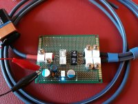
Hi, after many consultations, I think that the best way (from noise and jitter point of view) to commute a digital signal inside a DAC is through RF relays, even if are quite expensive.
In the case of SPDIF we should need a 75 ohm relay, and I found the OMRON G6Z-1F perfect, even if now obsolete.
The problem is that it only has one pole (SPDT), so it puts the grounds of the sources in common, which in my opinion is very bad.
So I used two pulse transformers, one for each source line, each terminated with 75 ohms, and only after that, I put the relay to switch the "hot" still having a common ground connection but now isolated: in this mode, grounds of the sources remain isolated from each other and from the DAC.
I have tested and it works perfectly without adding additional jitter.
Of course in order to don't jeopardize the work we need true 75 ohm cables and BNC connectors at input.
Also, as I don't want any possible induced RF noise close to the contacts, the coil is powered with a tiny voltage regulator (LE50) and RF filters. Comments if any, are welcome!
Attachments
Because even if a 74LVC1G3157 has outstanding performance, a relay like G6Z-1F wins because it has:Why not use a 2:1 analog multiplexer?
1) no jitter, since it is 3 GHz mechanical contact
2) no noise due to power supply because its coil is not part of the circuit path
3) no reflections since charateristic impedance is exactly 75 ohm
4) no distortion since input impedance is flat and not a function of input voltage
Also, by using an analog multiplexer you still need a pulse trafo to keep source grounds separated and very low noise power supply.
Hi I think you approach is the right one. Especially the cables of sources that are not chosen generally still have connection to SPDIF-GND which is undesirable. I solved it with switches switching both signal and GND but the static is a negative effect. Telling users to switch the device off before switching sources is silly.
So when is a PCB available ? 😉
So when is a PCB available ? 😉
Last edited:
Any benefit from using a 3GHz relay has been thrown away by your construction technique: long coax tails, ordinary perfboard. Fortunately the signal is quite robust so what you have demonstrated is that an ordinary relay fed from a noisy supply would have done the job just as well. You probably could have used an ordinary switch instead.
Positive comment, how nice. It seems a prototype to me (crocodile clips and the text indicate this well) and a proof of concept, not the final design. Compared to recent designs with obvious flaws that are praised here this idea seems ok.
Last edited:
He asked for comments. He didn't say it was a prototype. If you are worried about GHz frequencies then a prototype has to be built to high standards just like the real thing (but probably a bit less tidy).
It is your native language, not mine, and even I understand the proof of concept. No one worries about GHz while discussing SPDIF as that would be plain nonsense. OP clearly states:"(from noise and jitter point of view)".
Please reread the text of the OP. OP has found an elegant and simple mechanical/electrical way of switching sources without SPDIF GND of unused sources dangling in the air, no more no less. After experiments with IC's I also found that the simplest ways are again the best ways.
If we want to see high standards we better look at Nutube designs 😉
Last edited:
DF96 you are right. Jean-Paul, sorry, that it not a prototype: it will be really mounted on the (my) final machine.
But tails are the minimum to be soldered. Even if you use a PCB you have to cut coax in this way, if not the solid polyethylene dielectric melts or you make short-circuits once you move the cable.
Also, if you look carefully, I maintained the 2nd copper foil shield covering the inner conductor as much long as I could. Do you really think it is possible to have shorter shielded terminations using a PCB?
The inner conductors are soldered directly on the pulse transformer pins, at a distance of one hole, hence at 0.1 inch of spacing. The same the 75 ohm resistor. Even if you use a PCB you cannot make path shorter than this.
If you refer to the cable lengths, yes, those will be cut a lot once the board will be installed inside my DAC machine.
But be aware, if 75 ohm impedance will be maintained from the source (and all my components of the transmission line are done in this way: I will use exclusively BNC 75 ohm connectors, inner and external coax cable at 75 ohm, relay at 75 ohm, 1:1 75 ohm pulse transformer and 1% metallic 75 ohm resistor termination) the optimum total coax length is estimated to be between 2 and 5 meters (upon on internet guys experience) in order to minimise reflection's collateral effects, which you will have much more with shorter cables.
More length (>5m) is not recommendable due to losses.
Hence one feet of inner coax cable is not an issue till you maintain 75 ohm impedance matching; on the contrary it could even be beneficial in order to lower reflection's collateral effects.
S/PDIF: Does Coaxial Digital Cable Length Matter? - audiopolitan
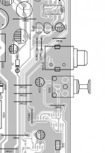
I immagine everybody knows how are the spdif coax output PCB inside ther majority of commercial players: full of bridges, long traces and random grounds paths (plus one RCA 😱): I wonder how much this has an impedance of 75 ohms better than my perfboard.
May be a switch works as well, I'm sure too, since as you said, SPDIF is quite roboust, but I've just done that best I could to minimize eventual issues, losses, reflections, noise and jitter from the source to the Dac receiver board.
But tails are the minimum to be soldered. Even if you use a PCB you have to cut coax in this way, if not the solid polyethylene dielectric melts or you make short-circuits once you move the cable.
Also, if you look carefully, I maintained the 2nd copper foil shield covering the inner conductor as much long as I could. Do you really think it is possible to have shorter shielded terminations using a PCB?
The inner conductors are soldered directly on the pulse transformer pins, at a distance of one hole, hence at 0.1 inch of spacing. The same the 75 ohm resistor. Even if you use a PCB you cannot make path shorter than this.
If you refer to the cable lengths, yes, those will be cut a lot once the board will be installed inside my DAC machine.
But be aware, if 75 ohm impedance will be maintained from the source (and all my components of the transmission line are done in this way: I will use exclusively BNC 75 ohm connectors, inner and external coax cable at 75 ohm, relay at 75 ohm, 1:1 75 ohm pulse transformer and 1% metallic 75 ohm resistor termination) the optimum total coax length is estimated to be between 2 and 5 meters (upon on internet guys experience) in order to minimise reflection's collateral effects, which you will have much more with shorter cables.
More length (>5m) is not recommendable due to losses.
Hence one feet of inner coax cable is not an issue till you maintain 75 ohm impedance matching; on the contrary it could even be beneficial in order to lower reflection's collateral effects.
S/PDIF: Does Coaxial Digital Cable Length Matter? - audiopolitan
I immagine everybody knows how are the spdif coax output PCB inside ther majority of commercial players: full of bridges, long traces and random grounds paths (plus one RCA 😱): I wonder how much this has an impedance of 75 ohms better than my perfboard.
May be a switch works as well, I'm sure too, since as you said, SPDIF is quite roboust, but I've just done that best I could to minimize eventual issues, losses, reflections, noise and jitter from the source to the Dac receiver board.
Attachments

Last edited:
I think this is the best you can do given the constraint that you want to build everything on perfboard.
If someone would build the same circuit on four-layer PCB with the signal traces designed as 75 ohm microstrip lines and with PCB-mounted SMA connectors on all in- and outputs, and measure both versions with a network analyser, the PCB version would probably behave better above 1 GHz. Then again, who cares?
If someone would build the same circuit on four-layer PCB with the signal traces designed as 75 ohm microstrip lines and with PCB-mounted SMA connectors on all in- and outputs, and measure both versions with a network analyser, the PCB version would probably behave better above 1 GHz. Then again, who cares?
, the PCB version would probably behave better above 1 GHz. Then again, who cares?
I think the issue is that the claim is that RF relays are required for this to work. And yet it works very well on a non-RF board.
The concept is good, just maybe it would work well with cheaper parts 😉 and I think is worth testing with other relays.
I agree when you want to mass-produce these circuits, but when the aim is to build only one of them and that one already exists, why waste money on cheaper relays?
Yes, my main point is that you don't need to worry too much about using a 75 ohm relay. If you think this really is needed then you need to find a 75 ohm coaxial relay with BNC connectors mounted on it - this will preserve impedance but is very unlikely to switch the ground too. Alternatively, don't worry about such things and just use a normal relay (or switch) and just keep the tails reasonably short. You seem to have said that you worry about impedance etc. but then have built a design which does not preserve impedance.ygg-it said:I immagine everybody knows how are the spdif coax output PCB inside ther majority of commercial players: full of bridges, long traces and random grounds paths (plus one RCA ): I wonder how much this has an impedance of 75 ohms better than my perfboard.
You seem to have said that you worry about impedance etc. but then have built a design which does not preserve impedance.
Where do you think I'm deviating from 75 ohm line impedance "much more" than anybody could do with a PCB? Is it my use of just 0.1 inch of perfbord (which is anyway sorrounded by pin soldered ground)? Again, which is the correct PCB design to preserve 75 ohm in traces?
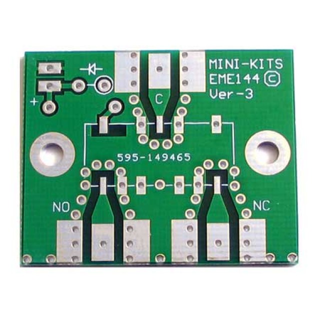
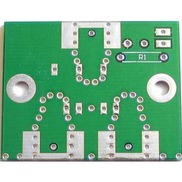
Like the attached one (be aware this is 50 ohm OMRON A-version relay and kit)? Are we sure it preserves its impedance due to the thickness of the board and the capacitance due to the ground plane? If this is 50 ohm impedance, how would be the thickness for 75 ohm PCB?
I think that the first place where I really lost 75 ohm is just before the input cap before the SPDIF receiver (AD8611/CS8412), but the 75 ohm coax was already terminated by the 75 ohm resistor, thus I don't think to have reflections after that resistor; and in any case like anybody else (even commercial DAC) would have.
2.6GHz Relay Kit
Last edited:
If you want to preserve impedance to high frequencies then you need to mount BNC connectors on the board and use microstrip techniques, or use a coaxial relay with BNC connectors - I'm not sure if they are available for 75R. Using a 50R relay just guarantees an impedance variation.
Putting a terminating resistor does not mean that anything after that can be ignored as it all appears in parallel with the resistor.
Putting a terminating resistor does not mean that anything after that can be ignored as it all appears in parallel with the resistor.
For the record, in post # 10, SMA should be SMB (or BNC or F or MCX or SMZ - any kind of small PCB-mounted RF connector available as 75 ohm versions).
The pieces of wire sticking out of the coaxial cables are basically transmission lines with a much higher characteristic impedance than the 75 ohm of the cable - much higher because the capacitance to the shield is far lower than inside the cable, and the characteristic impedance is sqrt(L/C). As long as these pieces are much shorter than a quarter of a wavelength, you can treat them as lumped inductances.
Order of magnitude estimate: according to the 1 nH/mm rule of thumb, with about 5 mm of wire sticking out of the coaxial cables and another 5 mm on the ground side, you have lumped inductances of the order of 10 nH. With 75 ohm, that gives you a corner frequency just below 1.2 GHz. Hence, the matching and bandwidth are limited by the wires rather than the relays; or actually that would be the case without transformers, it is quite likely that in reality the transformers will determine the bandwidth. Still, it's fine as long as the bandwidth is more than enough for an S/PDIF signal.
The PCB you've shown shows that there is also a problem preserving impedance with a PCB. The taper from the relay to the connector can't have the correct impedance everywhere; for a given PCB thickness and dielectric constant, there is only one width that results in 75 ohm (although you can tweak it a bit with the top layer ground fill). Still, you have to make a transition to the pin width of the connector somehow.
- Status
- Not open for further replies.
- Home
- Source & Line
- Digital Line Level
- DIY SPDIF splitter selector