What does the simplest possible Unity Gain Class AB Push-Pull Power Amplifier circuit look like?
For a cost-effective repair option I am looking for such a topology. Especially in cases, when the replace of STK-units or similar thickfilm parts not cost effective enough. But I want to have thermal stability by values arround 20-50mA for the idle current.
The disadvantage of the lack of voltage gain doesn't matter in some cases, particularly, when an active line stage with gain factor between 5-10 is present.
The only two circuits in this kind, that I know are in follow:
1) Andrea Ciuffoli's Cool Follower 99 - go to
Andrea Ciuffoli - Home Page
and
Quality in a Cool Follower 99
But in the circuit I miss a variable bias for fifferent quiscent current for the push-pull power devices
2) Anders Thule's "Virtual Class-A" - go to the pdf attachment in post #1 and last attachment in post #8 under
Ultimate ECC for Class B from Thule Audio? Topology also used by Teac
Because there is no global NFB, the front end is easy to remove for getting a unity gain power amp.
But in the first topology I miss the possibility of bias adjust and in the second the complexity is still too high for me for the wanted application.
Maybe there are even better circuits.
This threads don't provide the wanted information
simplest discrete really-unity gain buffer
Unity Gain Power Amplifier Voltage Gain = 1 (0 dB) - where are these amps ?
Thanks in advance for advices.
What does the simplest possible Unity Gain Class AB Push-Pull Power Amplifier circuit look like?
Are you really joking with such a poor goal?
What load?
What Vp-p?
What fT?
Are you really joking with such a poor goal?
What load?
What Vp-p?
What fT?
Is my english so bad ?
I am not planning a new amplifier project.
I only want to have a cost effective repair methody for amps with hard to find parts.
Ft and Vp-p is unknown and dependend from the respective model, which I get on the table for service.
Load is in general always 4-8 ohms
I think this is a good candidate compared to what you've already posted:
MJR7-Mk5 Mosfet Power Amplifier
MJR7-Mk5 Mosfet Power Amplifier
Hi
Wouldn't the simplest circuit be an EF2 or EF3? The input signal might have to be capacitively coupled because of the offset voltage of the BE junctions, but this would allow a DC servo to tickle the base-leak resistor. Bootstrapped resistive dividers might suffice for input current sources, if that is deemed as simpler than active ones?
In an EF3, the predriver could be flipped around as a diamond-like stage, still with biasing into the EF2 that follows.
How many stages there are depends on how light of a load you want the circuit to present to the driving opamp.
A variation would be to design it like a diamond buffer but have the output devices wired as CFPs for more current gain and better accuracy.
Lineup did a diamond feedback power buffer with low THD.
There are lots of people who want such a thing - a power buffer with no gain - and most want it to be simple if possible. BJTs are inexpensive but it does not actually take so many parts to build a buffer.
Even simpler would be a mosfet follower.
Last edited:
I only want to have a cost effective repair methody for amps with hard to find parts
Aaah!
Yes, but not so clearly.
Good amps are optimised for achievable low distortion and this straightly demand for very precise feedback frequency correction tuning.
All of that immediately demands for known wideband of exactly output stage.
As far as i understand unity gain - nauta are right and you can use simple EF2 or EF3(with its known stabilisation methods), also diamod buffer could be used while not so much power demanded.
But it will be better to realize two-three power output modules in some power steps. Say, 50, 100 and 200 Wt.
Pick simple and well optimized amp’s core, add service circuitry by your needs.
Pick simple and well optimized amp’s core, add service circuitry by your needs.
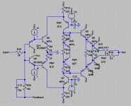
This is not buffer, input impedance are 2k and gain =5, but it's very simple and could be optimised for any goal.
Attachments
Unity gain stability is the issue. Otherwise simply adjusting the gain control resistors would work universally.
So any amplifier can be converted to unity gain but the frequency bandwidth increases (that is the gain bandwidth product) with falling gain and quickly reaches phase inversion frequency of, generally, the output transistors, and therefore, oscillation.
The frequency compensation must be adjusted (increased) to take the theoretical bandwidth increase into account. I have also found that severely limiting the input bandwidth (to the audio band) by adding capacitance across both of the shunt feedback resistors helps.
Unity gain stability is the issue.
Not the issue, there are very much sophisticated methods to curb any of the achieved feedback depth.
Otherwise simply adjusting the gain control resistors would work universally.
Ah, no, why dropout that very needed feedback depth?
Any of the circuits must be designed a step over, being stabilised on the threshold of stability with real margins.
Hey BesPav, I will be in St Petersburg for 2 days in a few months time. Really wanted to see and enjoy the Bolshoi in Moscow but alas. We will get to see the ballet in the Alexandriski Theatre however and thats almost as good. Plus the Heritage and Palaces etc. So looking forward to it.
And with respect to unity gain I simply refer to op amp first principles. The details depend on the actual amplifier of course.
And with respect to unity gain I simply refer to op amp first principles. The details depend on the actual amplifier of course.
Hey BesPav, I will be in St Petersburg for 2 days ...
Have a nice walk!
And with respect to unity gain I simply refer to op amp first principles. The details depend on the actual amplifier of course.
Aah! Got it.
Shown feedback circuitry allows to stabilize amp’s core being stable noninverting with gain up to 100.
😉
This is not buffer, input impedance are 2k and gain =5, but it's very simple and could be optimised for any goal.
In this amp the gain is source resistance dependent.
In this amp the gain is source resistance dependent.
Thank you for your input, Damir!
I supposed to have low output resistance of the source.
But you are clearly right and it was designed exactly for having well-approximated logarithmic volume regulation with simple, better quality and cheap linear potentiometer.
Not less than 100 dB regulation depth:

And...
Opamp based version are really better:
Opamp + Common base
😉
Last edited:
Thank you for your input, Damir!
I supposed to have low output resistance of the source.
But you are clearly right and it was designed exactly for having well-approximated logarithmic volume regulation with simple, better quality and cheap linear potentiometer.
Not less than 100 dB regulation depth:
View attachment 739706
And...
Opamp based version are really better:
Opamp + Common base
😉
You are making very interesting circuits for sure Pavel, but I still see the problem here. The potentiometer should be of low resistance, is it not? The DC current is going to flow through it and that's not good. I would add a buffer here.
You are making very interesting circuits for sure Pavel
Thank you for your kindness, Damir!
Your circuits are well-designed and very sophisticated too!
Sometimes i’m thinking about some kind of guide, but average level aren’t high enough, so let’s allow Douglas Self and Bob Cordell to carry their own crosses...
The DC current is going to flow through it and that's not good.
No, sinewave are biased for better look.
But really, we could add some DC for excluding croosover effects in the resistive alloy, wire alloy, wiper contact, etc...
We’ld subtract it later, somewhere at the load...
😉
The potentiometer should be of low resistance, is it not?
Yeah, logarithm have a two setting up parameters.
😉
~2k input and ~10k potz are good enough, not so low for loading previous source, not so high for excessive noise.
This is not buffer, input impedance are 2k and gain =5, but it's very simple and could be optimised for any goal.
It appears simple to someone used to understanding schematics, but non-technical builders will quickly see that it has 14 transistors, minus what you will need for the current and voltage sources. In contrast the MJR7 amp I linked to earlier has 7 transistors. Though despite the simplicity I haven't heard a single person say they've built one.
Both designs would have to be adjusted for unity gain however.
- Status
- Not open for further replies.
- Home
- Amplifiers
- Solid State
- What does the simplest possible Unity Gain Class AB PP Power Amp circuit look like ?