ZTX957/857 SOT223 for VAS. A little slower 300v - 85-100mhz - 13pf Cob.
But better than mje340/350 (or it's sot equivalent) .
You can hold SOT223 in your fingers , solder it's collector to a few square CM
of copper. 4ma VAS should stay cool.
Holton amps runs 4 exicon LATFET'S right from the VAS (223's) , looks like he
has about 9-10 cm2 copper foil dedicated each for the thermals.
OS
(like FB resistors or resistors and that have high voltages/powers across them).
12xx resistors work great, too, especially if you install parallel or series. All depends on one's FB resistance (well, more FB resistor dissipation, but I assume we're talking power amps here)
Mouser sells both Vishay and Susumu 1206's in pretty high precision at 1W rating (most are 1/4W). I've stuck with 1/4W rated.
DPH - yes with 1206 for preamp work I found no issue and thin-film types distortion is indistinguishable from a good leaded MF - just like 'Doug told us' 😉.
I use leaded (Mills) for the main feedback R in the big power amp. Its 10 W non-inductive non-magnetic type. For lower power amps, 5 or 6 0.5W leaded in parallel do a great job.
1W thick film types (I use 4.7 Ohms) make fantastic base stoppers BTW - you can mount them right next to the power output transistor bases.
Last edited:
My optimum domestic amp would be 200W 8R - 400W 4R .. not cos I won't clip it .. but cos if well designed, the clipping is usually un-noticed.
If you are using a 50W amp at home, you will be clipping it MUCH more often than you realise.
200-250W/8 will not clip in most people's home room size and average effec speakers. IMO there is No reason to build a low power amp.
THx-RNMarsh
Re: low cap diodes for clamping, isn't there a trade-off with the leakage current? Depending on the source impedance they are connected to, they can cause distortion just from the reverse leakage current.
For instance, while the BAV21 and the BAS212 are low cap, room temp Ileak is 100 to 150nA.
My current fav, the FDH300, is only 3nA typ, but has 6pF capacitance.
Depending on the surrounding circuitry there's a trade-off to be made.
Jan
For instance, while the BAV21 and the BAS212 are low cap, room temp Ileak is 100 to 150nA.
My current fav, the FDH300, is only 3nA typ, but has 6pF capacitance.
Depending on the surrounding circuitry there's a trade-off to be made.
Jan
Jan, suppose the BAV21's leakage varies between 1nA and 120nA as the reverse voltage across the diode changes, when the "VAS" node swings between (BotRail+3V) and (TopRail-3V).
If the transconductance of the VAS is about 40 mS (as in Cordell Figure 9.6-9.7) then an extra 120nA of signal at the VAS output, corresponds to (120nA / 40mS) = 3 uV at the VAS input.
Since the VAS input is the IPS output, 3uV at the VAS input corresponds to (3uV / IPSgain) at the amplifier input. Assuming a terrible current mirror, IPSgain is around 50 and so the corresponding signal at the amplifier input is 60 nanovolts.
Compared to a "normal line level" input of 250 millivolts, 60 nanovolts at the input is -132 dB down. Which might be difficult to detect with human hearing.
_
Last edited:
Thx to Mark for his calculation!
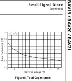
The onsemi/fairchild BAV21 has mostly lower as 5pf capacitance.
My current batch has about 0.8pF measuring 2 diodes in series (one reversed) with 1Vpp@10kHz and 1,6pF at 0.2Vpp@10kHz
Tested with my smart tweezer.
The capacitance decreases with higher reverse voltage. Have a look at the excerpt from the onsemi datasheet.
BTW: if you want to buy onsemi BAV21 - the status is last shipments via rochester.
BR, Toni
Attachments
Jan, suppose the BAV21's leakage varies between 1nA and 120nA as the reverse voltage across the diode changes, when the "VAS" node swings between (BotRail+3V) and (TopRail-3V).
[...]
_
Yeah that's a good point. My app was in the autoranger where there is a series R of a few k followed by the clamp. No feedback loop to correct things, so there it would be 1:1. I could clearly measure different distortion numbers depending on the diode leakage. At the -120dB level, clearly audible for most here ;-)
Jan
Re: low cap diodes for clamping, isn't there a trade-off with the leakage current? Depending on the source impedance they are connected to, they can cause distortion just from the reverse leakage current.
For instance, while the BAV21 and the BAS212 are low cap, room temp Ileak is 100 to 150nA.
My current fav, the FDH300, is only 3nA typ, but has 6pF capacitance.
Depending on the surrounding circuitry there's a trade-off to be made.
Jan
One way to mitigate this would be to run the VAS at a higher standing current so the leakage is a smaller percentage.
200-250W/8 will not clip in most people's home room size and average effec speakers. IMO there is No reason to build a low power amp.
THx-RNMarsh
Depends on your speakers. 20W class A with a pair of horns can sound amazing 😉
As always a good right up Bonsai,
1N4149 is another possibility 100V, 500mA, 25nA@20C, 4ns trr, 2pF max, DO-35
1N4149 is another possibility 100V, 500mA, 25nA@20C, 4ns trr, 2pF max, DO-35
As always a good right up Bonsai,
1N4149 is another possibility 100V, 500mA, 25nA@20C, 4ns trr, 2pF max, DO-35
Ahh - I will add that when I update it (which I always end up doing after I publish it 😉
I've captured some of the points re anti-sat diodes here.
Ahh - I will add that when I update it...
There's a minor typo on the second last slide (Antisatiration), but the content is to your usual standard, thanks for the write up.
Best wishes
David
Last edited:
I admit I still haven't read any of Self's books, but he has always put out a lot of info for free (thus I've wonder how much extra detail the books have, when his online articles appear to cover a lot already). Here's his "distortions in power amplifiers" page that I recall seeing online at least 20 years ago:
Distortion In Power Amplifiers - Home Warranty Appliances
Distortion In Power Amplifiers - Home Warranty Appliances

I've captured some of the points re anti-sat diodes here.
Nice overview, thanks!
Jan
Used this as "option a" on my blameless.
Same 13ppm with or without the clamping transistor (Q14).
"option B" (the diode) some were slightly better , all options just
a few ppm difference.
Both ways get the job done.
OS
Yes, I have used and still use that as well
I will add that to the write up in due course.
- Home
- Amplifiers
- Solid State
- Audio Power Amplifier by Douglas Self