Use smaller R1 to see if its a consumption issue? Like your config needs more current on the positive than the norm? You can piggyback in parallel on installed R1 for testing.
Hello Salas and all and thank you for proposing such a fantastic project ! I plan to use the modified version to use it as a +48V phantom power psu for microphones. I'm a little bit concerned about what I read earlier because typically I run microphone cables from 5 meters to 15-20M or sometimes more. Is there a matter to worry in my case ? Will I be able to use the Ultra BiB for this application ? Is it smart to anticipate a 1-2V voltage drop and output say 50V ? Phantom power is pretty tolerant and can accept up to 52V (actually the norm says 48V +/- 4V) Is there anything else I should be careful of ?
I will not power more than 8 microphones at the same time and max current draw for one mic will be 10ma, I plan to skip the 100ma current reserve as there is no peak of current so just to be safe, UBiB for my application will be 100ma. Concerning transformer sizing, if I plan to have 50V out and 10V voltage drop, I need to have a 60V out Tx correct ? Then following your recommendations, 60v x 0.1A x 3, I'll need a 18VA transformer, yes ?
Thank you very much in advance !
Last edited:
I have used 2.2R 3W for R1 so what do you suggest me to try with lower resistor value?
Well, a 3.3R on top of the 2.2R will make for 1.32R and allow 450mA current limit in your case.
By the way if your Soekris wants so much more on the positive rail than other examples shown here for no apparent reason like a startup peak due to extra caps maybe, or a special firmware setting, a peripheral sucking extra mA, etc. it should be alarming.
I.e. in case it has a non explicable over-current condition, its the regulator's current limiter that kept it away from a catastrophic fail.
Therefore I warn you that if your Soekris possibly has a problem it must be firstly diagnosed and fixed to not proceed feeding it with big step PSU current level allowances until it manages to self destruct.
Best way is to have a lab supply with current consumption reading in CC protection mode to incrementally up the limit finding out if it has a logically higher demand or what part of it is getting too hot, in other words to monitor if something is obviously wrong with it or not.
Or first ask the Soekris designer about your specific board revision in your personal configuration to positively know if it actually demands more than the 270mA start up +rail current that its your now PSU's current limit setting. That limit was enough for several builders examples in this thread and its weird your build seems not being covered.
Hello Salas and all and thank you for proposing such a fantastic project ! I plan to use the modified version to use it as a +48V phantom power psu for microphones. I'm a little bit concerned about what I read earlier because typically I run microphone cables from 5 meters to 15-20M or sometimes more. Is there a matter to worry in my case ? Will I be able to use the Ultra BiB for this application ? Is it smart to anticipate a 1-2V voltage drop and output say 50V ? Phantom power is pretty tolerant and can accept up to 52V (actually the norm says 48V +/- 4V) Is there anything else I should be careful of ?
I will not power more than 8 microphones at the same time and max current draw for one mic will be 10ma, I plan to skip the 100ma current reserve as there is no peak of current so just to be safe, UBiB for my application will be 100ma. Concerning transformer sizing, if I plan to have 50V out and 10V voltage drop, I need to have a 60V out Tx correct ? Then following your recommendations, 60v x 0.1A x 3, I'll need a 18VA transformer, yes ?
Thank you very much in advance !
That's a special application, I don't know if it will present any oddities because nobody that I know of used it like that up to now. The long cabling has enough resistance to negate the low output impedance benefit of this reg for one.
About causing instability I would not theoretically think so but that's only in theory. Matter of your will and curiosity to find out. I can't give any guarantee either for the higher voltage mod or this particular application. Both are untested propositions up to now.
You should leave the extra 100mA shunt current provision there i.e. set 180mA current limit to cover up to eight 10mA consuming mics because that extra is the regulator's own juice for good spec.
There is published resistance per meter spec for any established pro-grade branded mic cable and you can calculate the max voltage drop of each possible run in combination with the highest phantom power consuming mic in your arsenal, and allow for it.
After rectification a 43VAC transformer should bring about 59-60VDC at C1 i.e. at the regulator's DC input node.
Maybe you would consider using a Zener as the Vref to negate the lower going warm up output voltage drift of this reg when you want to control the lower limit of receiving end's voltage when expecting various drops due to long cabling vs a changing population of hooked up mics of various mA spec in various recording sessions.
Salas, I was wondering about a potential feature. Is it within our current engineering knowledge to construct a shunt regulator that has both rails track each other very closely, maybe to 0.01%? Or is there a workaround that can provide dual rail and also very low impedance?... Just quite curious from speculations in the dam1021 thread...
Edit: both rails can have the same cc setting. I’m not sure if you are sufficiently interested in digital audio but my theory is that the Vref in Soekris R2R can cause significant changes in timbre (as opposed to pitch or amplitude) that cannot be sufficiently measured using our current test suites, which almost exclusively focuses on pitch and amplitude correctness. I shared some academic sources in the dam1021 thread that seems to support such a speculation, where it is suggested that there could be as many as 34 dimensions to timbre compared to only 1 for pitch and 1 for amplitude, which we test all too thoroughly. There’s also some corroborating evidence from TotalDAC’s development and testing, but I’m more inclined to believe that they just went all out on everything.. which in this case might’ve did them some good. If you have time I would very much love to hear your intuitions on this matter... thanks for any help!
Edit: both rails can have the same cc setting. I’m not sure if you are sufficiently interested in digital audio but my theory is that the Vref in Soekris R2R can cause significant changes in timbre (as opposed to pitch or amplitude) that cannot be sufficiently measured using our current test suites, which almost exclusively focuses on pitch and amplitude correctness. I shared some academic sources in the dam1021 thread that seems to support such a speculation, where it is suggested that there could be as many as 34 dimensions to timbre compared to only 1 for pitch and 1 for amplitude, which we test all too thoroughly. There’s also some corroborating evidence from TotalDAC’s development and testing, but I’m more inclined to believe that they just went all out on everything.. which in this case might’ve did them some good. If you have time I would very much love to hear your intuitions on this matter... thanks for any help!
Last edited:
Have you tried powering the Soekris without the add-on board that you have installed? In case it draws considerable power that you have not accounted for.I have double checked the Soekris DAC board and actually redid the mounting today with all nylon spacers and nylon screws.
Actually I'm not even sure if I want you to answer my first question... Maybe your free advice will end up in some commercial product that doesn't deserve it... Anyway, ideally there can be a crowdfunded community effort but nothing has to happen... I proposed some experiments on the dam1021/1121 to obtain some empirical evidence for the idea but who knows if anyone with the necessary recording/measurement equipment might be interested. 🙁
I guess I'm getting overly attached to and concerned about an idea whose validity I'm in no position to show. Curiosity and the excitement for discoveries are wonderful, but sometimes you still gotta be careful. At this point I think I've shared most of my thoughts about potential improvements on that thread, and the community will makes its own decisions about how and whether to move forward... Don't worry about getting back to me!
I guess I'm getting overly attached to and concerned about an idea whose validity I'm in no position to show. Curiosity and the excitement for discoveries are wonderful, but sometimes you still gotta be careful. At this point I think I've shared most of my thoughts about potential improvements on that thread, and the community will makes its own decisions about how and whether to move forward... Don't worry about getting back to me!
Have you tried powering the Soekris without the add-on board that you have installed? In case it draws considerable power that you have not accounted for.
Hi DimDim
I am powering the input board separately via the Salas Ref-D board with +7v. As I do not have anything else apart from the Amanero I2S DAC which is again USB powered and does not take any power from the input board as such not sure what is that needs more current as the same setup with Salas 1.1 boards work perfectly without any issues.
So I am just figuring out why the positive board drops the voltage, one reason I can think of is that the negative board with 62R 22W load resistor cannot go beyond the -9.5v but without the load or powering the Soekris DAC the negative voltage is stable @ -12v, so maybe the dac is trying to pull the max from the positive board.
Thanks
Why not also measure voltage drops across all BJT JFET MOSFET (Vbe Vgs) in positive and negative reg builds to compare and see if any semiconductor shows something wrong on the positive board so to replace it.
If all is well then all it remains is to allow more current limit through the positive. BiB 1.1 had more shunt current allowance.
If all is well then all it remains is to allow more current limit through the positive. BiB 1.1 had more shunt current allowance.
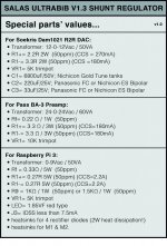
Special parts value summary:
Hi all,
I just got Teabag's boards and I had gone through the first 50 pages of reading; information was everywhere; so I made a quick summary for the special parts' values since I have a Soekris Dam1021 DAC, RPI3 with linear PS and building a BA-3 preamp right now.
If there is any mistake, let me know I will correct it.
Attachments

 thank you
Well, a 3.3R on top of the 2.2R will make for 1.32R and allow 450mA current limit in your case.
I just tried with a parallel resistor of 3.3R first and the voltage was stable on the positive board when powered to Soekris DAC. Then I changed the 3.3R to 2.2R in parallel and its stable as well. So its like taking around 500mV across R1 on the positive board when powered with soekris board.
It's good that you got it working, but ATM you don't know whether you have enough (spare) CCS current for proper operation.
If I were you I'd measure the current consumption of each Soekris rail with some other power supply. That way you will be able to accurately calculate your necessary UBiB CCS current.
If I were you I'd measure the current consumption of each Soekris rail with some other power supply. That way you will be able to accurately calculate your necessary UBiB CCS current.
I just tried with a parallel resistor of 3.3R first and the voltage was stable on the positive board when powered to Soekris DAC. Then I changed the 3.3R to 2.2R in parallel and its stable as well. So its like taking around 500mV across R1 on the positive board when powered with soekris board.
Is Q1 BC327 indeed and not BC337 by mistake? Those have tiny print and can be mixed up by mistake.
Is Q1 BC327 indeed and not BC337 by mistake? Those have tiny print and can be mixed up by mistake.
Its BC327 only which came with the Tea-Bag kit of +IRF parts and not BC337 so all parts look exactly as per the manual with no discrepancy.
The negative supply uses 337 so they can be confused if not observed carefully, that is why I mentioned. So you had 595mV voltage drop on R1 before and now 500mV? That's bit odd.
The negative supply uses 337 so they can be confused if not observed carefully, that is why I mentioned. So you had 595mV voltage drop on R1 before and now 500mV? That's bit odd.
Sorry I meant that I had 595mV voltage drop on R1 with paralleling either 2.2R or 3.9R additionally on top of the existing 2.2R. So the voltage drop across R1 is consistently 595mV.
- Home
- Amplifiers
- Power Supplies
- Salas SSLV1.3 UltraBiB shunt regulator