Hello! I`m basically building a replica of the great ess heil amt for my university project implementing Digital filters and class D power amplifier.
In order to get my project done, I would like opinions and constructive feedback on what I`m doing and the materials. This will be my first project using transducers so I`m happy to listen to ur advice.!
In order to get my project done, I would like opinions and constructive feedback on what I`m doing and the materials. This will be my first project using transducers so I`m happy to listen to ur advice.!
still available
Did you know that you can still buy them? They are not expensive but they are heavy.
Maybe they aren't as much fun to reverse engineer...
Did you know that you can still buy them? They are not expensive but they are heavy.
Maybe they aren't as much fun to reverse engineer...
Attachments

Last edited:
It was in the 1980 issue of the Audio Amateur Loudspeaker Projects
Published by: Audio Amateur, Incorporated, USA 1980
ISBN 10: 0833801937 / ISBN 13: 9780833801937
I was gonna build one but never did.
I actually made all made most of the parts and was working on construction methods for the Diaphragm and got a huge stack of magnets that ended up in a build for a straight ribbon driver.
But then again I was more in to the the Roger Sanders ESL projects at the time that are in it as well. 😉
jer 🙂
Last edited:
It is not an exact replica, I only decided to go with a similar diaphragm which I`ll fabricate this week.
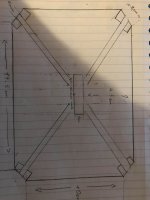
I was referring to the Ess amt because I picked their idea with those metal strips on the diagonals where I`ll have the magnets. Let me show you what I mean.
I was referring to the Ess amt because I picked their idea with those metal strips on the diagonals where I`ll have the magnets. Let me show you what I mean.
Attachments


amt envelope&magnets structure
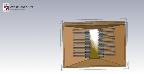
When I referred to the ESS amt I wanted to say that I picked up and idea from their structure of metal strips on the diagonal. Instead of using massive ceramic magnets on the 4 sides as they did, I`ll use small neodymium magnets placed in between metals stips position close to the diaphragm.
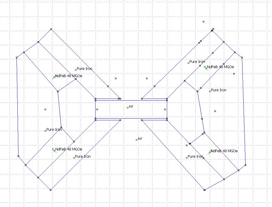
In the following photos is a design made but not finished to simulate de magnetic flux ....but I still have trouble getting access to a full license for the software from the university.( is very hard to simulate such a structure)
When I referred to the ESS amt I wanted to say that I picked up and idea from their structure of metal strips on the diagonal. Instead of using massive ceramic magnets on the 4 sides as they did, I`ll use small neodymium magnets placed in between metals stips position close to the diaphragm.
In the following photos is a design made but not finished to simulate de magnetic flux ....but I still have trouble getting access to a full license for the software from the university.( is very hard to simulate such a structure)
Attachments

bottom
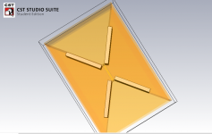
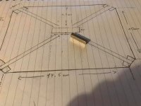
Here is a drawing with some dimensions where I decided to cut the corner of the envelope so a better fixing of the magnets&iron will be possible on a flat surface also with channels on the bottom and top of the walls.
All the parts will be laser cut on 6mm wood.( 2 pieces will be glued together to get a thickness of 12mm)
Attachments
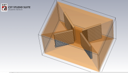
Now the problem I have in my design is that because I could not simulate the magnetic flux I don`t know if it will work with the magnets I have.
As magnets, I`m using neodymium magnets(4.3 kg pull) 25mm long 5mm wide x5mm thick ( 70 in total, around 17 per wall). Those magnets will be placed between steel plates 7.5mm long x 13mm wide x 3mm thick.
The reason I use 3mm thick steel plates is just to get more magnets in the structure.
The magnetic structure will be inserted in a laser cut plastic board made to exactly fixed both magnets and steel plates dimensions and also fixed with some silicon to ensure that are no vibrations from the plastic.
Anyway, what are your thoughts on the magnets I used and the way they will be placed at the very end close to the diaphragm? are they too small? Should I place them a bit far from the diaphragm?
Attachments
For the magnets I`m thinking to go only with the steel strips 1cm over the membrane each side and the magnets in between will be placed just where the diaphragm ends so I`ll not cover the membrane at all.( only the steel strips will be a bit 1cm over to ensure an even magnetic flux even on the middle of the diaphragm.
Also, do you have any suggestions for the diaphragm I have to design??
As materials, I have 30um aluminum and 5um and 10 um mylar. For the aluminum coil, I`ll use a CNC machine.
I`m thinking and I`ll design this week a membrane of 140mm high and 40mm wide after folding (not including the frame of the membrane).
Since I don`t have too much time to practice lots of sizes or combinations of 2 membranes I`m happy to listen to your suggestion. ( **I`m time limited since I have to finish this project until April this including class D power amplifier and digital filters )
I did a simulation on the Kithara AMT, which I think is similar to the Heil AMT.
An externally hosted image should be here but it was not working when we last tested it.
An externally hosted image should be here but it was not working when we last tested it.
An externally hosted image should be here but it was not working when we last tested it.
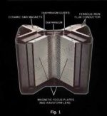
Yes I know the simulation but the heil AMT uses huge blocks of ceramic magnets behind those metal flat bars( as shown below in the picture). In my design, I`m using small neodymium magnets placed in between those metal strips but I think I`ll get enough magnetic flux around the membrane.
Anyway, do you have any suggestion of membrane dimension pleat depth and the ratio I should try with this design?
Anyway, do you have any suggestion of membrane dimension pleat depth and the ratio I should try with this design?
Attachments
Can you supply me with views similar to the first one in my post above?
On the Heil AMT and your design, it should be fairly easy to design.
Regarding pleat depth and width, I did some measurement on a couple of Båndsei AMTs that might give you a clue.
There is also of course plenty of measurements in the other DIY AMT threads.
What frequency range are you aiming for?
What's your distortion target?
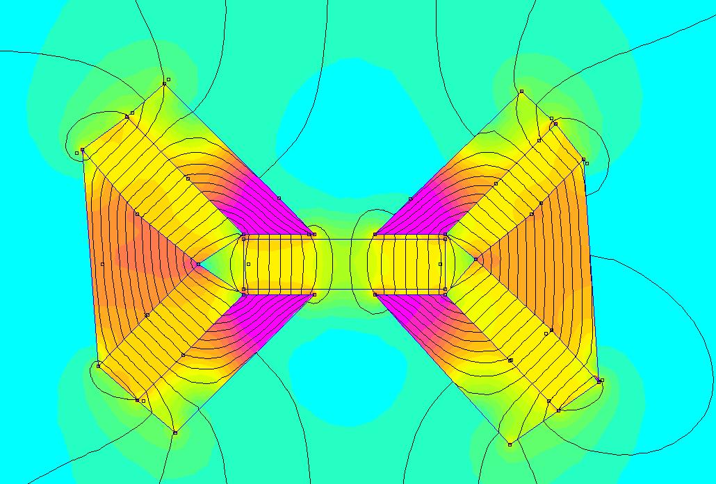
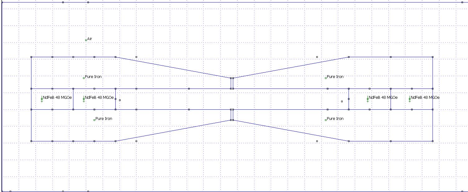
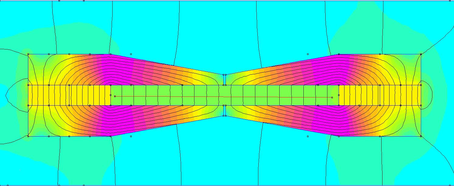
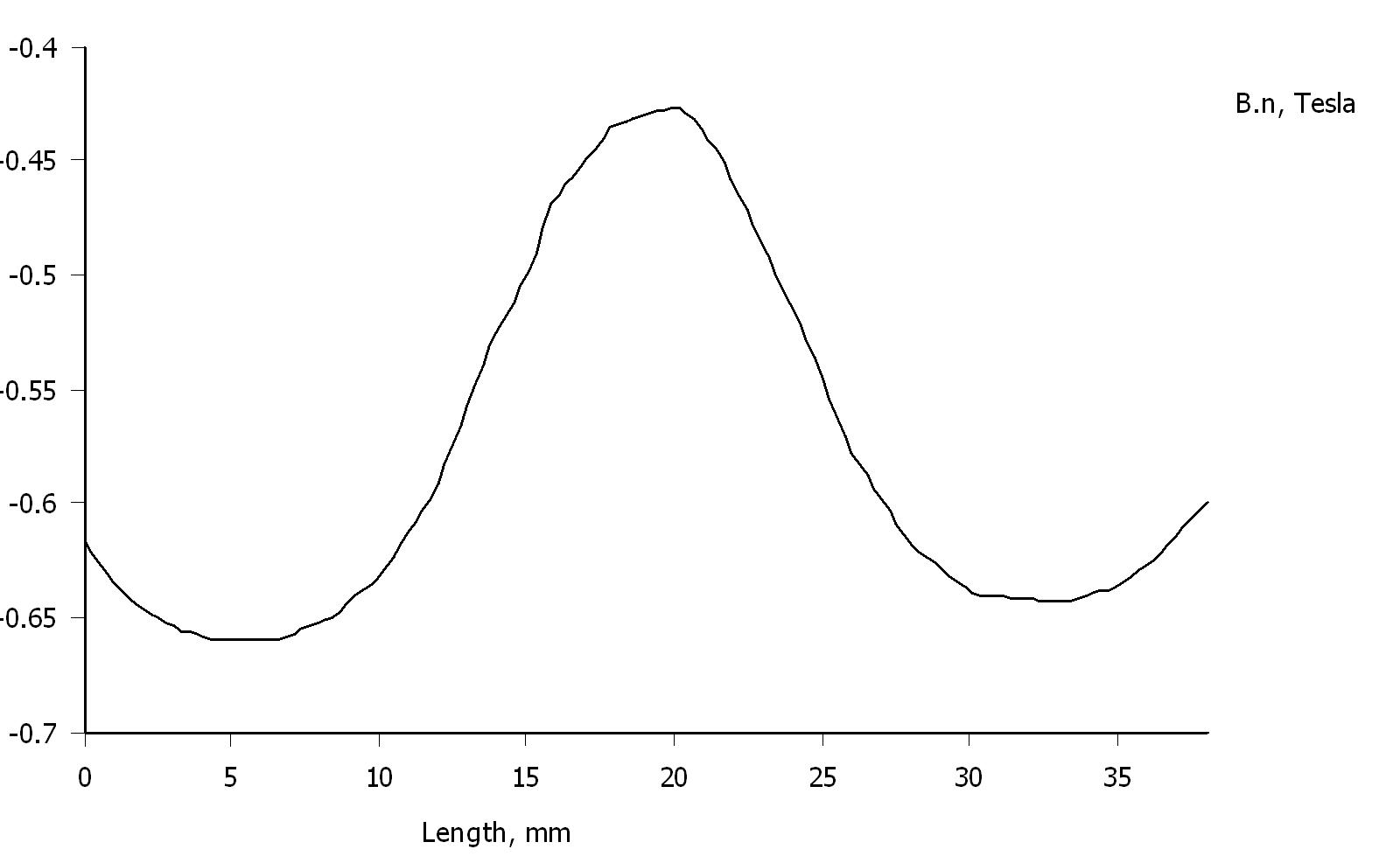
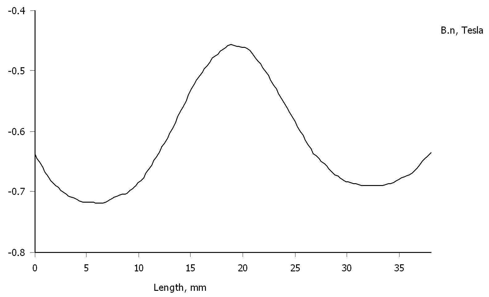
I looked at the Heil patent and made these very crude attempts:
Unmodified Heil:
Magnets closer to gap:
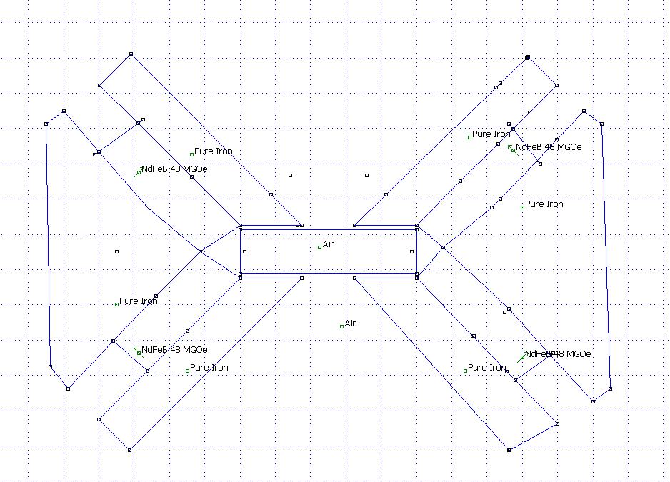
No pole pieces at the end:
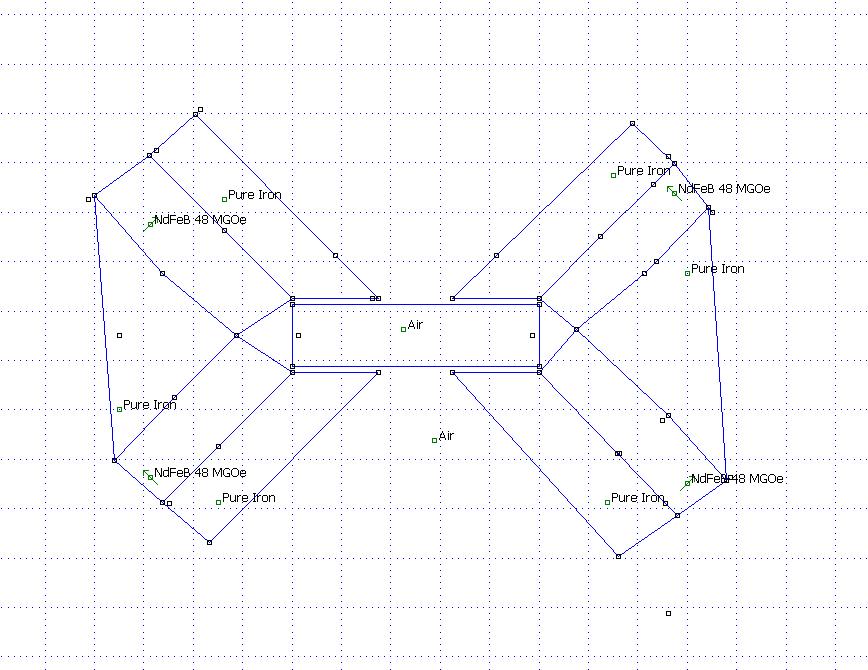
Note that the magnets are very strong.
Unmodified Heil:
Magnets closer to gap:
No pole pieces at the end:
Note that the magnets are very strong.
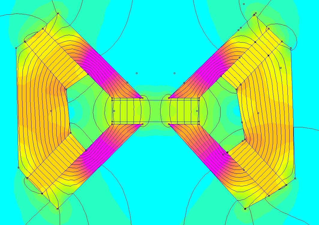
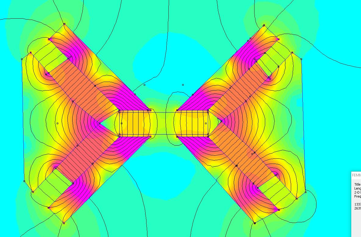
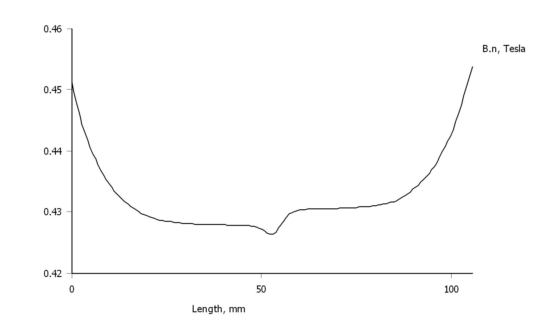
Flux density in the gap:
An externally hosted image should be here but it was not working when we last tested it.
An externally hosted image should be here but it was not working when we last tested it.
An externally hosted image should be here but it was not working when we last tested it.
J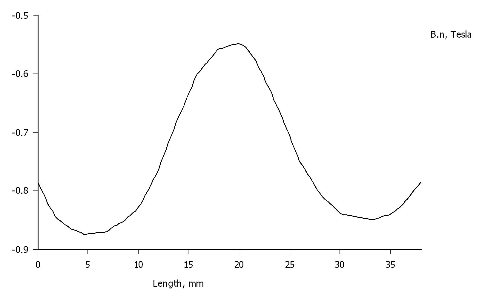
Hello! The simulation looks great. Thanks!
What software did you use? I would like to check my design since I changed a lot in the structure.
Also tomorrow I`ll post photos with the design of the envelope made in AutoCAD ready for laser cutting.
What software did you use? I would like to check my design since I changed a lot in the structure.
Also tomorrow I`ll post photos with the design of the envelope made in AutoCAD ready for laser cutting.
- Status
- Not open for further replies.
- Home
- Loudspeakers
- Planars & Exotics
- Air motion transformer (replica of the great ESS Heil AMT)