any chance anyone may have a schematic for the ovation 6051 preamp made in the early 70's? i picked one up, would like to restore it but a little leery about it without a schematic with my present level of knowledge.
read that dumb as a stump 😉
any help/leads would be appreciated!!
this was the weird "head" with two channels, reverb, fuzz and tremolo
its also known as the 6100, as seen in this vintage catalog
http://www.ovationtribute.com/Catalogues/Brown Amps Catalog/Amp Catalog.PDF
also the first pic on this page:
Ovation amps

sucks that when fender closed ovation down here in ct they threw literally all the stuff from the history of ovation out
if anyone can help me in my search, i'd be very grateful!!!
read that dumb as a stump 😉
any help/leads would be appreciated!!
this was the weird "head" with two channels, reverb, fuzz and tremolo
its also known as the 6100, as seen in this vintage catalog
http://www.ovationtribute.com/Catalogues/Brown Amps Catalog/Amp Catalog.PDF
also the first pic on this page:
Ovation amps
sucks that when fender closed ovation down here in ct they threw literally all the stuff from the history of ovation out
if anyone can help me in my search, i'd be very grateful!!!
I'd reach out to ovation. You might get lucky. These amps are very rare and I don't know of any schematics available for any of their amplifiers.
This may help as a pre amp is just a pre amp and I doubt Ovation changed the design much over the years.
http://www.ovationtribute.com/Ovation%20Schematics/Ovation_Optima_Pre-Amps_Schematic/Ovation_Optima_Pre-Amps_Schematic.pdf
http://www.ovationtribute.com/Ovation%20Schematics/Ovation_Optima_Pre-Amps_Schematic/Ovation_Optima_Pre-Amps_Schematic.pdf
This may help as a pre amp is just a pre amp and I doubt Ovation changed the design much over the years.
http://www.ovationtribute.com/Ovation%20Schematics/Ovation_Optima_Pre-Amps_Schematic/Ovation_Optima_Pre-Amps_Schematic.pdf
That's for an onboard guitar preamp. Their preamp/amp heads were a whole other beast of their own. I have worked on a k-6100, but it's been 15 years probably.
yeah, this amp has several different possible names depending on which enclosure etc. its def a k-6001 preamp.
i live in ct, where ovations were made. when fender bought it, they ruined the place, and when they closed it, they literally threw away the entire history in the place... all the parts, instruments, amps, speakers etc.
used to be you could call them up and get almost anything they'd made for free or a very reasonable price. now its all gone.
fender has nothing. ovation has nothing. kaman aerospace, the parent company of ovation, has nothing.
the ovation tribute site DOES have the owners manual, which shines some lite on the circuit, but no schematics.
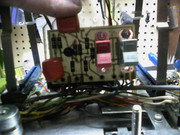
at this point, i've got it open and pulled apart and mostly working.
the ONE STAGE not on an "amplicard" is the final one, the mixer stage.
it appears to have been modified, likely by the factory, to do something here. it looks like they may have intentionally shorted it at the factory, it sounds like playing thru say, an old kustom with blown output. it will still pass signal and you can hear most of the stuff in it, but a very low volume.
i've been posting about it on aron nelson's forum, diystompboxes, and so far, its definitely tracked down to the mixer stage.
we're hoping to resurrect the fuzz in it to a standalone pedal as its really nasty and harsh sounding and may be fun.
its a really weird unit. almost everything in it is wired in parallel, so if one part goes down, the rest will keep working.
at this point, i have both preamps working and passing signal, but the channel 2 output is easily 12db or so louder than the channel 1 and 2 outputs. so either its a design flaw, or that one unmarked button q on the mixer board next to the reverb switches is cooked.
we'll see... still working on it. stay tuned!
i live in ct, where ovations were made. when fender bought it, they ruined the place, and when they closed it, they literally threw away the entire history in the place... all the parts, instruments, amps, speakers etc.
used to be you could call them up and get almost anything they'd made for free or a very reasonable price. now its all gone.
fender has nothing. ovation has nothing. kaman aerospace, the parent company of ovation, has nothing.
the ovation tribute site DOES have the owners manual, which shines some lite on the circuit, but no schematics.
at this point, i've got it open and pulled apart and mostly working.
the ONE STAGE not on an "amplicard" is the final one, the mixer stage.
it appears to have been modified, likely by the factory, to do something here. it looks like they may have intentionally shorted it at the factory, it sounds like playing thru say, an old kustom with blown output. it will still pass signal and you can hear most of the stuff in it, but a very low volume.
i've been posting about it on aron nelson's forum, diystompboxes, and so far, its definitely tracked down to the mixer stage.
we're hoping to resurrect the fuzz in it to a standalone pedal as its really nasty and harsh sounding and may be fun.
its a really weird unit. almost everything in it is wired in parallel, so if one part goes down, the rest will keep working.
at this point, i have both preamps working and passing signal, but the channel 2 output is easily 12db or so louder than the channel 1 and 2 outputs. so either its a design flaw, or that one unmarked button q on the mixer board next to the reverb switches is cooked.
we'll see... still working on it. stay tuned!
This may help as a pre amp is just a pre amp and I doubt Ovation changed the design much over the years.
http://www.ovationtribute.com/Ovati...hematic/Ovation_Optima_Pre-Amps_Schematic.pdf
ha ha,,, a preamp is just a preamp?🙄
naaaaaaaah 😉😉
not this one. i guarantee you'll never see ANYTHING like this sucker bro.😀
btw, there's like, 40 different versions of onboard ovation preamps, there's the accoustic guitars, which have a bunch, there's the old electrics and basses which also had their own, all completely different, and of course these standalone beasts like the one i'm working on.
there's a lot of history to ovation most folks are oblivious to, as they stopped producing amplification around 1972 to focus on strung up salad bowls.
the amps are built like brick shithouses. strong, simple, really well laid out and designed with many unusual features for the time.
i mean, at this time, how many commercial guitar pre amps had two channels with summed inputs and featured onboard reverb, fuzz, tremolo and top boost for each channel and footswitching for the effects, and true stereo output capabilities? fuggedabouddit!😀
so... nope, not all preamps are basically the same.
this has nothing in common with any preamp you've likely seen before.
i'd post ya some links for info, but, there's really nothing out there.
on the ovation tribute site, you can read the 6001 model preamp manual, which will give ya a little bit of pertinant info, but... we got more info in the thread at aron's so far than the whole bloody web.😱
ovation fuzz from the late 60's/// help me resurrect it?
lotta pictures, of all the proprietary boards, the guts, the chassis etc etc, and should have a working unit soon. i doubt i'll have the patience to do a proper schematic, as its all flying leads to computer style sockets for everything, and kinda like working inside a hammond organ, if you're familiar with them. real pia.
anyways! thanks for the suggestion!!
Post some images of the area in question, if you can. If you have a multi meter, we may be able to walk you through diagnosing the issues.
thanks lex,
already posted a **** load of pics on aron's, its in the link.
i am already pretty far along in the repair, and know where and what the problem is... a factory messup solder bridge in the mixer stage at the end before the output. the only part thats hardwired in the amp other than the power supply... everything else is on cards, very much like the venerable haynes jazz king amp.
i was just hoping to find a schematic to make it easier, but i've already tested all the boards and cleaned it and got it working 95% or so. just need to finish the last. not sure how to add pics here without uploading them somewhere else and linking. thaats why i put the link to the thread on diystompboxes above somewhere. it would take me a couple hours just to link all the stuff already uploaded. seriously. lotta pix!!
the entire circuit is ptp, so its pretty easy to follow without a schematic, was just hoping i could look at one. conversely, there's so many freekin wires inside its like working in a hammond organ, so probably won't be drawing one up.
just trust me... its very freekin weird! 😉
this post in particular shows the problem area, but believe me, this isn't what anything else you've likely seen is. EVERYTHING except the power supply and the output mixer is in parallel, for one. very very strange unit! 😉
ovation fuzz from the late 60's/// help me resurrect it?
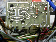
this is the problem area. looks like they f'd up the right side, where the transistor is, and tried to add resistors to get it to bias.
the left side is mostly just the switching for the reverb circuits
all the deets uncovered so far are in the link above...
thanks so much for checking in on this tho!!
yes, i have a multimeter, and a sig gen and an o-scope and an audio probe and all kindsa other **** i barely know how to use 😉
most of the time, i just follow the old jack darr ways, as i read the guy my whole life.
huge fan of the circuit disturbance test... you know, when ya whack the bejesus out of it to see if it f's up 😉
looks so far like the biggest issue is gonna be identifying the suspect q, as its an old-school LARGE button style (about as big as a sharpie is around) with no markings on it whatsoever.
i can pull it to test it, but if its bad, i ain't got the first clue how to find a valid replacement 😉
unless i sacrifice the tremolo card, which appears to use the same q's
already posted a **** load of pics on aron's, its in the link.
i am already pretty far along in the repair, and know where and what the problem is... a factory messup solder bridge in the mixer stage at the end before the output. the only part thats hardwired in the amp other than the power supply... everything else is on cards, very much like the venerable haynes jazz king amp.
i was just hoping to find a schematic to make it easier, but i've already tested all the boards and cleaned it and got it working 95% or so. just need to finish the last. not sure how to add pics here without uploading them somewhere else and linking. thaats why i put the link to the thread on diystompboxes above somewhere. it would take me a couple hours just to link all the stuff already uploaded. seriously. lotta pix!!
the entire circuit is ptp, so its pretty easy to follow without a schematic, was just hoping i could look at one. conversely, there's so many freekin wires inside its like working in a hammond organ, so probably won't be drawing one up.
just trust me... its very freekin weird! 😉
this post in particular shows the problem area, but believe me, this isn't what anything else you've likely seen is. EVERYTHING except the power supply and the output mixer is in parallel, for one. very very strange unit! 😉
ovation fuzz from the late 60's/// help me resurrect it?
this is the problem area. looks like they f'd up the right side, where the transistor is, and tried to add resistors to get it to bias.
the left side is mostly just the switching for the reverb circuits
all the deets uncovered so far are in the link above...
thanks so much for checking in on this tho!!
yes, i have a multimeter, and a sig gen and an o-scope and an audio probe and all kindsa other **** i barely know how to use 😉
most of the time, i just follow the old jack darr ways, as i read the guy my whole life.
huge fan of the circuit disturbance test... you know, when ya whack the bejesus out of it to see if it f's up 😉
looks so far like the biggest issue is gonna be identifying the suspect q, as its an old-school LARGE button style (about as big as a sharpie is around) with no markings on it whatsoever.
i can pull it to test it, but if its bad, i ain't got the first clue how to find a valid replacement 😉
unless i sacrifice the tremolo card, which appears to use the same q's
Looks like you are on the right path. The only thing that really sticks out to me is that PCB. I'll attach the spot. You mentioned this. If there is no actual trace there, I would remove that glob of solder that is laying over the two traces and see if that doesn't cure some of the woes.
Attachments
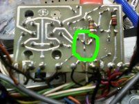
yessir, exactly what we were thinking. what they did was tack resistors on the bottom of the board to try and get more gain out of it, but... i think they shorted the damn b to ground ... that bridge goes directly to the ground connection to that board bro. it was most def done at the factory, i think they fudged the design, cuz if ya use just the "channel two only" output its about 2x as loud as the summed outputs. i don't think they considered the crosstalk issues of having two channels merged basically passively.
without the paperwork, the world may never know!! lol
but i intend to find out. dealing with some health issues right now or i'd be on it already like white on rice.
thanks for the support man!
without the paperwork, the world may never know!! lol
but i intend to find out. dealing with some health issues right now or i'd be on it already like white on rice.
thanks for the support man!
Good luck with the health of you and the amp...you 1st of course.
The old Peavey 400 series amps were all in parallel like this and it made for an interesting mission when diagnosing issues.
The old Peavey 400 series amps were all in parallel like this and it made for an interesting mission when diagnosing issues.
i remember them!! yeah, its harder than a series circuit, for sure.. but i am for sure the problem is that one board... i've already cleaned everything, and tested each of the plug in boards. the problem stays with the socket, not the channel cards, i can put either one in channel 2 and they will work fine. in "mono" output, the volume is low, but both channels work, reverb works on both, trem, etc.. when ya split it, the reverb goes to the summed outputs only, the dry signal comes out channel two with the fuzz, and the wet signal from channel one goes out. they split the signals at the output jacks.
did i mention its weird? 😉
did i mention its weird? 😉
- Status
- Not open for further replies.
- Home
- Live Sound
- Instruments and Amps
- ovation guitar preamp 6051