Thanks to a member here who posted how he fixed the problem with these little amps. They were mistakenly manufactured with a 100ohm resistor instead of a 3K resistor, putting the amplifiers gain @300.
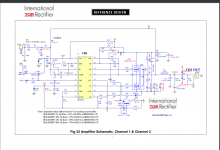
According to the OP, R8 is 130K instead of 120K as in the IRAUDAMP7S reference design here.
Also, according to Page 29, Gain = R8/R2. Isn't it really Gain = R8/(R2+R7)? I say this because 120,000/(3000+330) = 36.
I would like to modify the Gain to maximize this Amp's potential with an input signal of only .9Vrms. These amps are rated at 1.5Vrms with a gain of 36, according to the reference design. These China boards are closer to 40.
Attachments
Well, since no advice was given here and after talking to an EE friend, I decided to order 2.5K resistors in 0805 package. This will put the gain @ 130,000/(2500+330) = 46. I'll try to take some pre and post pics with the 'scope.
I'm with you. The R8/R2 is a misprint and should have been R8/(R7+R2) as stated earlier in the document.
How did the 2.5K resistors ever work out?
Was there a noticeable increase in gain?
I will have time this Monday to do comparisons w/pics.
Arggh. I'm not getting around to do this mod because these keep blowing out! So far I've had 4 fail. The fan stops blowing and no output. Thankfully it doesn't harm the speakers.
So taking 1 apart the FET they are using is a IRFB31N20D. Any help?
So taking 1 apart the FET they are using is a IRFB31N20D. Any help?
- Status
- Not open for further replies.